7/8″ Corrugated
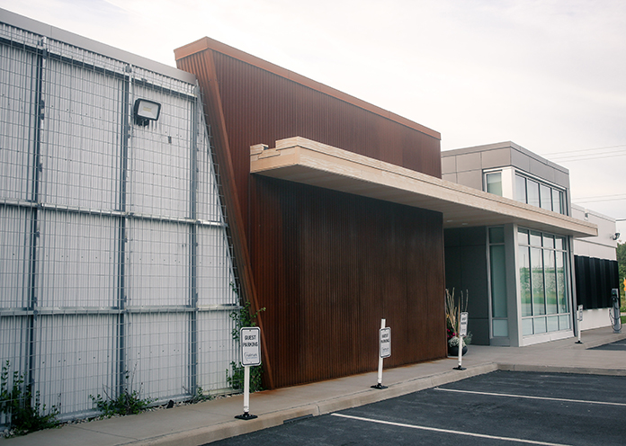
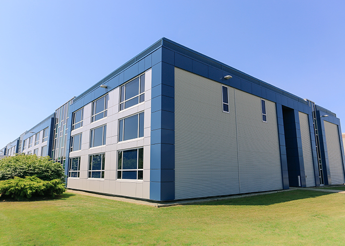
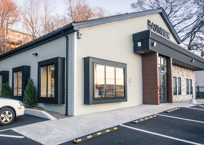
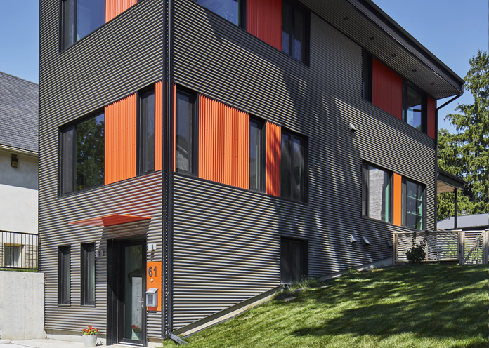
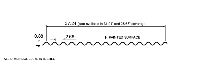
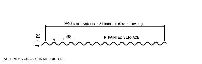
Very popular among architects, Agway’s 7/8” Corrugated profile features panels with exposed fasteners and no hard lines, resulting in a highly consistent appearance and a more organic overall look. Panels are available in a variety of widths, thicknesses and finishes.
Measurement Type
Profile Picture
1. Steel conforms to ASTM A653.
2. Section properties are in accordance with CSA-S136-07.
3. Values in row “S” are based on strength.
4. Values in row “D” are based on a deflection limit of 1/180 of the span.
5. Web crippling not included in strength values. See example calculation in notes to designer.
6. Contact the sales department for stocked colours and gauges.
7. The load table contained on this data sheet was prepared by Dr. R.M. Schuster P.Eng. Professor Emeritus of Structural Engineering, University of Waterloo, Ontario, Canada.
Specifications
| GAUGE | LENGTH | COVERAGE | ||
|---|---|---|---|---|
| MINIMUM | MAXIMUM | MINIMUM | MAXIMUM | |
| 28 | 18 | 30 | 780 | 37.25 |
| 28 | 18 | 30 | 780 | 31.94 |
| 30 | 18 | 30 | 780 | 26.59 |
| GAUGE | LENGTH | COVERAGE | ||
|---|---|---|---|---|
| MINIMUM | MAXIMUM | MINIMUM | MAXIMUM | |
| 28 | 18 | 762 | 19.81 | 946.2 |
| 28 | 18 | 762 | 19.81 | 811.28 |
| 30 | 18 | 762 | 19.81 | 675.39 |
Section Properties
| BASE STEEL THICKNESS |
WEIGHT G90 |
YIELD STRESS |
SECTION MODULUS |
DEFLECTION MOMENT OF INERTIA |
|
|---|---|---|---|---|---|
| in | psf | ksi | MID SPAN in 3 |
SUPPORT in 3 |
MID SPAN in 4 |
| 0.018 | 1.00 | 33 | 0.0566 | 0.0566 | 0.0248 |
| 0.024 | 1.32 | 33 | 0.0743 | 0.0743 | 0.0325 |
| 0.030 | 1.64 | 33 | 0.0913 | 0.0913 | 0.0399 |
| 0.036 | 1.95 | 33 | 0.108 | 0.108 | 0.0471 |
| 0.048 | 2.58 | 33 | 0.139 | 0.139 | 0.0607 |
| BASE STEEL THICKNESS |
MASS Z275 |
YIELD STRESS |
SECTION MODULUS |
DEFLECTION MOMENT OF INERTIA |
|
|---|---|---|---|---|---|
| mm | kg/m | MPa | MID SPAN x10 3mm3 |
SUPPORT x10 3mm3 |
MID SPAN x10 3mm3 |
| 0.457 | 4.90 | 230 | 3.04 | 3.04 | 0.0338 |
| 0.610 | 6.44 | 230 | 3.99 | 3.99 | 0.0444 |
| 0.762 | 7.99 | 230 | 4.91 | 4.91 | 0.0545 |
| 0.914 | 9.53 | 230 | 5.79 | 5.79 | 0.0643 |
| 1.22 | 12.6 | 230 | 7.46 | 7.46 | 0.0829 |
