Sub-Girts
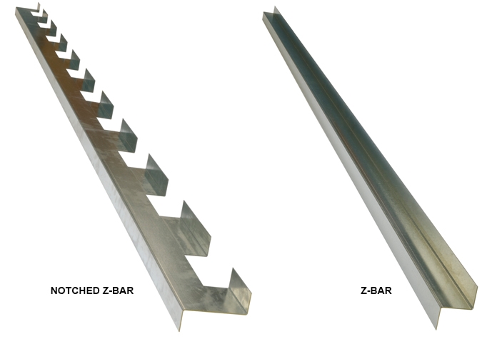
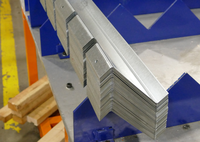
Substructural Sub-Girts are used extensively in the attachment of roofing, siding, and soffits to a structure. Available components include Z-bars, Notched Z-Bars, Hats, Channels, Angles – which represent the broadest selection of cold-formed substructural components in the industry. Brake formed lengths are available in 10’, 16’ and 20’ lengths. Our roll formed Sub-Girts allow any custom lengths to be produced.
Standard Breakshapes

- Available in 22 to 12 Gauge Galvanized G-90 Grade 33
- Available in 10’, 16’ and 20’ lengths
- Length capabilities up to 20’
- Custom lengths available
Custom Operations
- Punching and Notching
- Brackets and Clips
- Flat Straps
- Custom Notched Bars to match any Cladding/Roofing Profile
Materials
- Stock – Galvanneal, Galvanized, Galvalume and Prepainted
- Also available in Aluminum and Stainless Steel
Roll Form Production
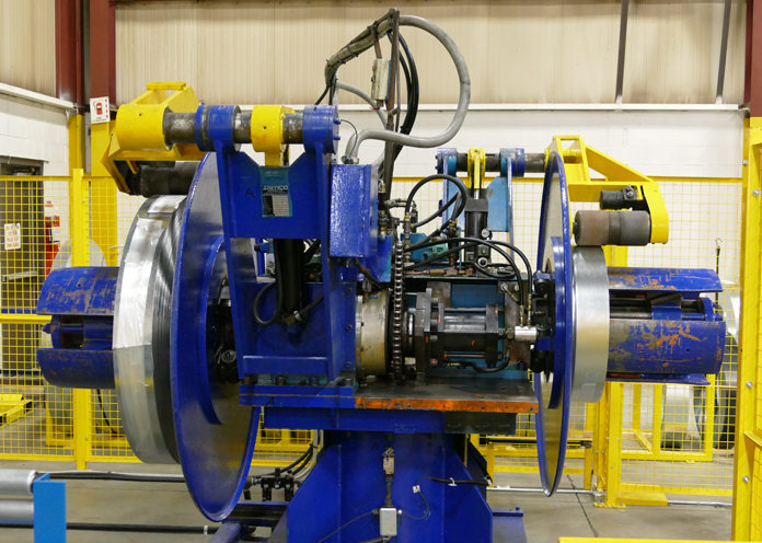
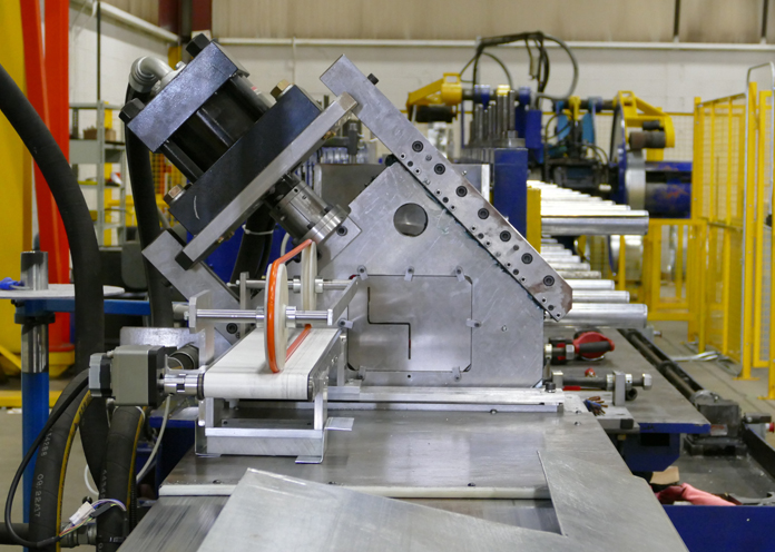
Agway has added new mills dedicated to the roll-forming of a variety of sub-girts. These mills augment the existing brake-formed sub-girt production.
Advantages:
- Roll-forming components leads to faster turnarounds and quicker delivery to the job site
- Produce all of the standard sub-girt forms in lengths of 10’, 16’ and 20’ with the added advantage of custom lengths up to 30’
- Automated pre punch, with the ability to punch ¼” holes on 4” centres on one flange/leg of a girt section.
- Can be used to produce our eave starter product, with a quick tooling change over
Pre Punch
The following forms are available for pre punch:
- 90º Angle
- Channel
- Z-Bar (notched and plain)
- U-Channel
Pre Punch Options:
- Random dimension from leading edge, holes punched 4” pitch, max length 30’
- First hole starts at 2” from leading edge, holes punched 4” pitch, last hole 2” from trailing edge. 10’ length only
Note: Holes will be positioned in the centre of the flange as standard. Custom positions are available upon request for an additional set up charge.
Exceptions for pre punched forms:
The following list of girt products that have a projection of less than 2” will not have the option of pre punched holes:
- 7/8” Z-Bar
- 1” Z-Bar
- 1 ½” Z-Bar
- 7/8” Hat Bar
- 1” Hat Bar
- 1 ½” Hat Bar
Brake Formed Sub-Girts
Z-Bar
| Standard in 10′ 0″ (3048 mm Lengths) |
Notched for AL-315 Profile in 31″ Lengths |
 |
| NO | NO | DIMENSION X |
| Z-75 | – | 3/4″ (19 mm) |
| Z-100 | – | 1″ (25 mm) |
| Z-150 | NZ-150 | 1-1/2″ (38 mm) |
| Z-200 | NZ-200 | 2″ (51 mm) |
| Z-250 | NZ-250 | 2-1/2″ (64 mm) |
| Z-300 | NZ-300 | 3″ (76 mm) |
| Z-350 | NZ-350 | 3-1/2″ (89 mm) |
| Z-400 | NZ-400 | 4″ (102 mm) |
| Z-450 | NZ-450 | 4-1/2″ (114 mm) |
| Z-500 | NZ-500 | 5″ (127 mm) |
| Z-550 | NZ-550 | 5-1/2″ (140 mm) |
| Z-600 | NZ-600 | 6″ (152 mm) |
| Z-650 | NZ-650 | 6-1/2″ (165 mm) |
| Z-700 | NZ-700 | 7″ (178 mm) |
| Z-750 | NZ-750 | 7-1/2″ (191 mm) |
| 7-800 | NZ-800 | 8″ (204 mm) |
U-Bar
| Standard in 10′ 0″ (3048 mm Lengths) |
 |
| NO | DIMENSION X |
| U-75 | 3/4″ (19 mm) |
| U-100 | 1″ (25 mm) |
| U-150 | 1-1/2″ (38 mm) |
| U-200 | 2″ (51 mm) |
| U-250 | 2-1/2″ (64 mm) |
| U-300 | 3″ (76 mm) |
| U-350 | 3-1/2″ (89 mm) |
| U-400 | 4″ (102 mm) |
| U-450 | 4-1/2″ (114 mm) |
| U-500 | 5″ (127 mm) |
| U-550 | 5-1/2″ (140 mm) |
| U-600 | 6″ (152 mm) |
| U-650 | 6-1/2″ (165 mm) |
| U-700 | 7″ (178 mm) |
| U-750 | 7-1/2″ (191 mm) |
| U-800 | 8″ (204 mm) |
Hat Section
| Standard in 10′ 0″ (3048 mm Lengths) |
 |
|
| NO | DIMENSION X | DIMENSION YY |
| H-62 | 5/8″ (16 mm) | 1-1/2″ (38 mm) |
| H-75 | 3/4″ (19 mm) | 1-1/2″ (38 mm) |
| H-100 | 1″ (25 mm) | 1 – 1/2″ (38 mm) |
| H-150 | 1-1/2″ (38 mm) | 1-1/2″ (38 mm) |
| H-200 | 2″ (51 mm) | 2″ (51 mm) |
| H-250 | 2-1/2″ (64 mm) | 2-1/2″ (64 mm) |
| H-300 | 3″ (76 mm) | 3 ” (76 mm) |
- 18 Gauge Galvanized is standard.
- 16 or 14 Gauge available on request.
- Available in 10’-0”, 16’-0” and 20’-0” lengths.
- Custom sizes (not shown) can also be produced.
- Custom lengths available.


