Agway Thermal Clip (ATC)
Agway Thermal Clip (ATC) provides support for cladding panels while acting as a thermal break in exterior insulated walls. The clips are made from 16 gauge galvanized steel lined with cork tape, a material known for its insulating properties. The Thermal Clips are paired with Sub Girt L Bars, which are positioned to fit the thickness of the insulation panels and can support vertical and horizontal cladding in a variety of wall compositions. Thermal bridging is prevented by the cork tape facilitating energy saving goals.
Span Tables for 4” Agway Thermal Clip (ATC)

The spacing shown above are based on the following,
- Analysis of the bracket, girts and mechanical attachments are in general accordance with the National Building Code of Canada (NBCC) using Limit State Design (LSD).
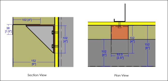
- Thermal Clip: 4” by 4” by 2.5” 16ga. thermally broken clip (ASTM A653 CS Type B, G-90 ( Z275 ), min yield stress = 33ksi).
- Girt Type: 4” x 1-1/2” 16ga. G-90 ( Z275 ) (min yield stress = 33ksi).
- Girt to Thermal Clip Fasteners: (2) # 14 x 1″ Self Drilling Galvanized Screws per bracket.
- Concrete Substrate Anchor: (2) ¼” Tapcon screw anchors (min. embedment = 1-1/2”, f’c = 2000 psi).
- 5 psf [0.24 kN/m2] dead load with exterior face of panel at 5-3/4” when measured from concrete substrate.
- Components were analyzed based on 1.25D + 1.4W load combination using the nominal loads listed above.
- Vertical and horizontal girt deflections limited to 0.125” and L/60 respectively.
- Table 1: Thermal Transmittance of the Evaluated Wall Assembly
The table above is intended to provide an estimated allowable spacing for the brackets and is not to be used for construction. Analysis of the bracket, girt and mechanical attachments was conducted by MORRISON HERSHFIELD. Results have not been verified by finite element analysis or testing. Calculations stamped by a licensed engineer should be provided on a project by project basis to ensure all components meet the local code requirements.
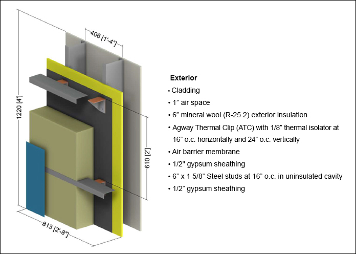
Example Vertical Wall Assembly

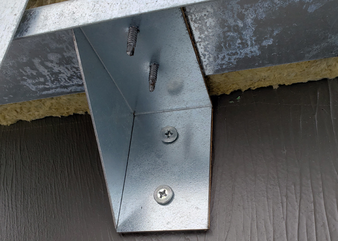
Thermal Clip Horizontal Girt Arrangement


