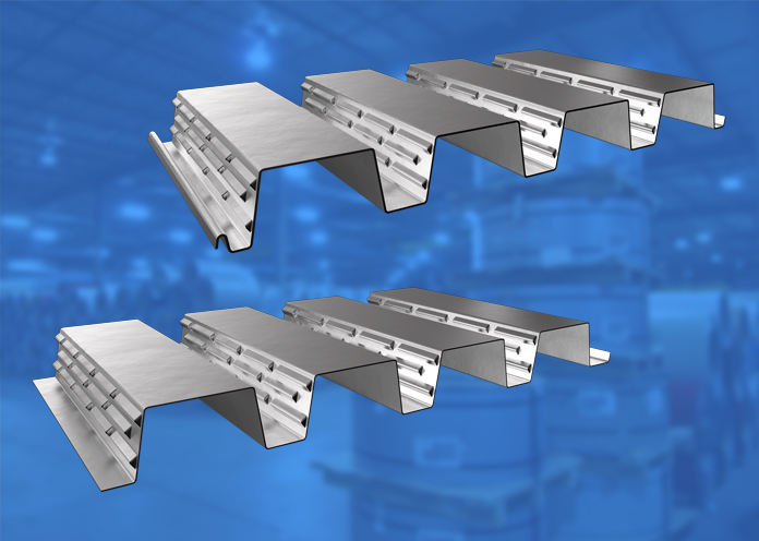
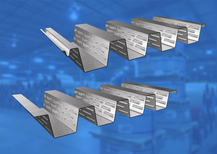
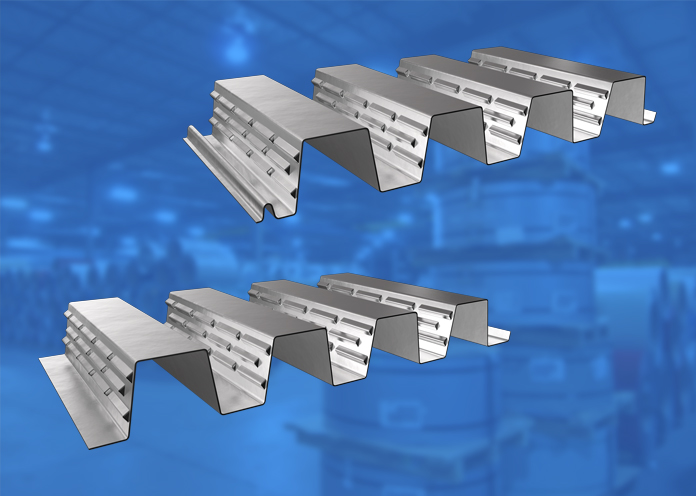
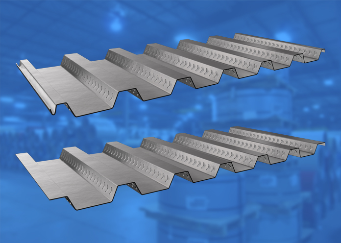
CD75-200 | CD75-200 CL Galvanneal
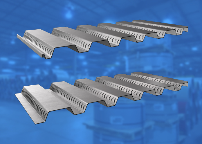
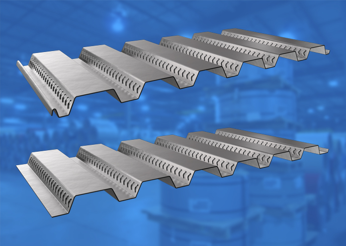
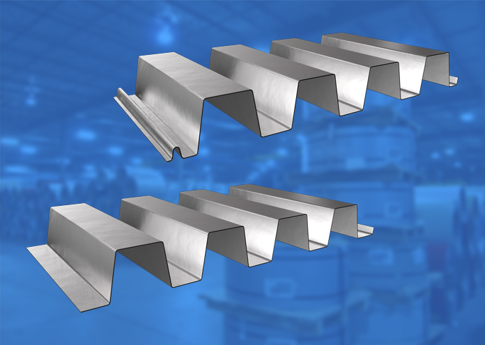
The CD75-200 deck section features 3” flutes spaced 8” apart, with embossments rolled into the web elements that interlock with concrete to form an extremely lightweight, unified composite structure offering superior strength-to-weight ratios. In addition to supporting gravity loads, hybrid composite decks offer superb lateral diaphragm action, thereby reducing or eliminating the need for structural bracing against lateral loads, such as winds, hydrostatic pressures, and even earthquakes.
Agway CD deck sections are listed in the following ULC floor assemblies: F817; F904; F906.
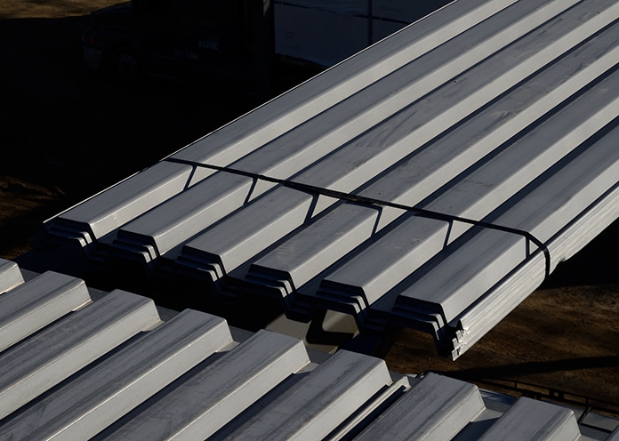
Bundled deck produced from either Galvanneal or G90 Galvanized coated steel is susceptible to storage stain when exposed to the elements. This staining is superficial only and is not a valid reason for rejection of this product.
For more information, refer to CSSBI Fact Sheet #33
Measurement Type
Profile Picture


Specifications
| GAUGE | LENGTH | COVERAGE | ||
|---|---|---|---|---|
| MINIMUM | MAXIMUM | MINIMUM | MAXIMUM | |
| 22 | 16 | 48" | 600" | 32" |
| GAUGE | LENGTH | COVERAGE | ||
|---|---|---|---|---|
| MINIMUM | MAXIMUM | MINIMUM | MAXIMUM | |
| 22 | 16 | 1219.2 mm | 15.24 m | 813 mm |
Section Properties
| BASE STEEL THICKNESS |
WEIGHT G90 |
AREA OF STEEL |
YIELD STRESS |
SECTION MODULUS |
DEFLECTION MOMENT OF INERTIA |
|
|---|---|---|---|---|---|---|
| in | psf | in2 |
ksi | MID SPAN in 3 |
SUPPORT in 3 |
MID SPAN in 4 |
| 0.030 | 2.08 | 0.594 | 33 | 0.375 | 0.397 | 0.677 |
| 0.036 | 2.48 | 0.712 | 33 | 0.485 | 0..503 | 0.880 |
| 0.048 | 3.29 | 0.95 | 33 | 0.675 | 0.724 | 1.27 |
| 0.060 | 4.10 | 1.19 | 33 | 0.862 | 0.904 | 1.64 |
| BASE STEEL THICKNESS |
MASS Z275 |
AREA OF STEEL |
YIELD STRESS |
SECTION MODULUS |
DEFLECTION MOMENT OF INERTIA |
|
|---|---|---|---|---|---|---|
| mm | kg/m | in2 |
MPa | MID SPAN x10 3mm3 |
SUPPORT x10 3mm3 |
MID SPAN x10 3mm3 |
| 0.762 | 10.1 | 1257 | 230 | 20.1 | 21.3 | 0.922 |
| 0.914 | 12.1 | 1507 | 230 | 26.0 | 27.0 | 1.20 |
| 1.220 | 16.1 | 2010 | 230 | 36.2 | 38.8 | 1.73 |
| 1.520 | 20.0 | 2513 | 230 | 46.3 | 48.6 | 2.24 |
Composite Slab Properties
| OVERALL SLAB DEPTH, D (IN) | ||||
|---|---|---|---|---|
| 5.0 | 5.5 | 6.0 | 6.5 | 7.0 |
| SLAB WEIGHT (PSF) | ||||
| 41.5 | 47.8 | 54 | 60.3 | 66.5 |
CONCRETE VOLUME (YD3/100FT2) |
||||
| 0.92 | 1.08 | 1.23 | 1.39 | 1.54 |
| OVERALL SLAB DEPTH, D (MM) | ||||
|---|---|---|---|---|
| 130 | 140 | 150 | 160 | 170 |
| SLAB WEIGHT (KPA) | ||||
| 1.98 | 2.21 | 2.43 | 2.66 | 2.68 |
CONCRETE VOLUME (M3/10M2) |
||||
| 0.79 | 0.89 | 0.99 | 1.09 | 1.19 |
CD75-150 | CD75-150 CL Inverted Galvanneal
The CD75-150 deck section features 3” flutes spaced 6” apart, with embossments rolled into the web elements that interlock with concrete to form an extremely lightweight, unified composite structure offering superior strength-to-weight ratios. In addition to supporting gravity loads, hybrid composite decks offer superb lateral diaphragm action, thereby reducing or eliminating the need for structural bracing against lateral loads, such as winds, hydrostatic pressures, and even earthquakes.
Agway CD deck sections are listed in the following ULC floor assemblies: F817; F904; F906.
Bundled deck produced from either Galvanneal or G90 Galvanized coated steel is susceptible to storage stain when exposed to the elements. This staining is superficial only and is not a valid reason for rejection of this product.
For more information, refer to CSSBI Fact Sheet #33
Measurement Type
Profile Picture


Specifications
| GAUGE | LENGTH | COVERAGE | ||
|---|---|---|---|---|
| MINIMUM | MAXIMUM | MINIMUM | MAXIMUM | |
| 22 | 16 | 48" | 600" | 24" |
| GAUGE | LENGTH | COVERAGE | ||
|---|---|---|---|---|
| MINIMUM | MAXIMUM | MINIMUM | MAXIMUM | |
| 22 | 16 | 1219.2 mm | 15.24 m | 610 mm |
Section Properties
| BASE STEEL THICKNESS |
WEIGHT G90 |
AREA OF STEEL |
YIELD STRESS |
SECTION MODULUS |
DEFLECTION MOMENT OF INERTIA |
|
|---|---|---|---|---|---|---|
| in | psf | in2 |
ksi | MID SPAN in 3 |
SUPPORT in 3 |
MID SPAN in 4 |
| 0.030 | 2.34 | 0.672 | 33 | 0.492 | 0.485 | 0.906 |
| 0.036 | 2.80 | 0.806 | 33 | 0.623 | 0.621 | 1.10 |
| 0.048 | 3.71 | 1.07 | 33 | 0.898 | 0.882 | 1.46 |
| 0.060 | 4.63 | 1.34 | 33 | 1.12 | 1.12 | 1.82 |
| BASE STEEL THICKNESS |
MASS Z275 |
AREA OF STEEL |
YIELD STRESS |
SECTION MODULUS |
DEFLECTION MOMENT OF INERTIA |
|
|---|---|---|---|---|---|---|
| mm | kg/m | in2 |
MPa | MID SPAN x10 3mm3 |
SUPPORT x10 3mm3 |
MID SPAN x10 3mm3 |
| 0.762 | 11.4 | 1421 | 230 | 26.4 | 26.0 | 1.24 |
| 0.914 | 13.7 | 1705 | 230 | 33.4 | 33.3 | 1.50 |
| 1.220 | 18.1 | 2274 | 230 | 48.2 | 47.4 | 2.00 |
| 1.520 | 22.6 | 2843 | 230 | 60.0 | 60.3 | 2.49 |
Composite Slab Properties
| OVERALL SLAB DEPTH, D (IN) | ||||
|---|---|---|---|---|
| 5.0 | 5.5 | 6.0 | 6.5 | 7.0 |
| SLAB WEIGHT (PSF) | ||||
| 50.5 | 56.8 | 63.0 | 69.3 | 75.5 |
CONCRETE VOLUME (YD3/100FT2) |
||||
| 1.13 | 1.29 | 1.44 | 1.60 | 1.75 |
| OVERALL SLAB DEPTH, D (MM) | ||||
|---|---|---|---|---|
| 130 | 140 | 150 | 160 | 170 |
| SLAB WEIGHT (KPA) | ||||
| 2.39 | 2.62 | 2.84 | 3.07 | 3.30 |
CONCRETE VOLUME (M3/10M2) |
||||
| 0.96 | 1.06 | 1.16 | 1.26 | 1.36 |
CD75-150 | CD75-150 CL Galvanneal
The CD75-150 deck section features 3” flutes spaced 6” apart, with embossments rolled into the web elements that interlock with concrete to form an extremely lightweight, unified composite structure offering superior strength-to-weight ratios. In addition to supporting gravity loads, hybrid composite decks offer superb lateral diaphragm action, thereby reducing or eliminating the need for structural bracing against lateral loads, such as winds, hydrostatic pressures, and even earthquakes.
Agway CD deck sections are listed in the following ULC floor assemblies: F817; F904; F906.
Bundled deck produced from either Galvanneal or G90 Galvanized coated steel is susceptible to storage stain when exposed to the elements. This staining is superficial only and is not a valid reason for rejection of this product.
For more information, refer to CSSBI Fact Sheet #33
Measurement Type
Profile Picture


Specifications
| GAUGE | LENGTH | COVERAGE | ||
|---|---|---|---|---|
| MINIMUM | MAXIMUM | MINIMUM | MAXIMUM | |
| 22 | 16 | 48" | 600" | 24" |
| GAUGE | LENGTH | COVERAGE | ||
|---|---|---|---|---|
| MINIMUM | MAXIMUM | MINIMUM | MAXIMUM | |
| 22 | 16 | 1,219.2 mm | 15.24 m | 610 mm |
Section Properties
| BASE STEEL THICKNESS |
WEIGHT G90 |
AREA OF STEEL |
YIELD STRESS |
SECTION MODULUS |
DEFLECTION MOMENT OF INERTIA |
|
|---|---|---|---|---|---|---|
| in | psf | in2 |
ksi | MID SPAN in 3 |
SUPPORT in 3 |
MID SPAN in 4 |
| 0.030 | 2.34 | 0.672 | 33 | 0.485 | 0.492 | 0.866 |
| 0.036 | 2.80 | 0.806 | 33 | 0.621 | 0.623 | 1.07 |
| 0.048 | 3.71 | 1.07 | 33 | 0.882 | 0.898 | 1.46 |
| 0.060 | 4.63 | 1.34 | 33 | 1.12 | 1.12 | 1.82 |
| BASE STEEL THICKNESS |
MASS Z275 |
AREA OF STEEL |
YIELD STRESS |
SECTION MODULUS |
DEFLECTION MOMENT OF INERTIA |
|
|---|---|---|---|---|---|---|
| mm | kg/m | in2 |
MPa | MID SPAN x10 3mm3 |
SUPPORT x10 3mm3 |
MID SPAN x10 3mm3 |
| 0.762 | 11.4 | 1421 | 230 | 26.0 | 26.4 | 1.18 |
| 0.914 | 13.7 | 1705 | 230 | 33.3 | 33.4 | 1.46 |
| 1.220 | 18.1 | 2274 | 230 | 47.4 | 48.2 | 2.00 |
| 1.520 | 22.6 | 2843 | 230 | 60.0 | 60.3 | 2.49 |
Composite Slab Properties
| OVERALL SLAB DEPTH, D (IN) | ||||
|---|---|---|---|---|
| 5.0 | 5.5 | 6.0 | 6.5 | 7.0 |
| SLAB WEIGHT (PSF) | ||||
| 46.2 | 52.5 | 58.7 | 65.0 | 71.2 |
CONCRETE VOLUME (YD3/100FT2) |
||||
| 1.03 | 1.18 | 1.34 | 1.49 | 1.64 |
| OVERALL SLAB DEPTH, D (MM) | ||||
|---|---|---|---|---|
| 130 | 140 | 150 | 160 | 170 |
| SLAB WEIGHT (KPA) | ||||
| 2.20 | 2.42 | 2.65 | 2.87 | 3.10 |
CONCRETE VOLUME (M3/10M2) |
||||
| 0.88 | 0.98 | 1.08 | 1.18 | 1.28 |
CD36 | CD36 CL Inverted Galvanized
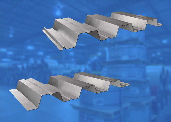
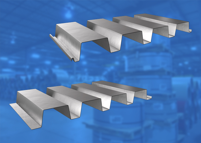
Agway CD deck sections feature embossments rolled into the flutes, which interlock with concrete to form an extremely lightweight, unified composite structure offering superior strength-to-weight ratios. In addition to supporting gravity loads, hybrid composite decks offer superb lateral diaphragm action, thereby reducing or eliminating the need for structural bracing against lateral loads, such as winds, hydrostatic pressures, and even earthquakes.
Agway CD deck sections are listed in the following ULC floor assemblies:
F816; F817; F904; F906.
Bundled deck produced from either Galvanneal or G90 Galvanized coated steel is susceptible to storage stain when exposed to the elements. This staining is superficial only and is not a valid reason for rejection of this product.
For more information, refer to CSSBI Fact Sheet #33
Measurement Type
Profile Picture


Specifications
| GAUGE | LENGTH | COVERAGE | ||
|---|---|---|---|---|
| MINIMUM | MAXIMUM | MINIMUM | MAXIMUM | |
| 22 | 18 | 36" | 540" | 36" |
| GAUGE | LENGTH | COVERAGE | ||
|---|---|---|---|---|
| MINIMUM | MAXIMUM | MINIMUM | MAXIMUM | |
| 22 | 18 | 914 mm | 13.72 m | 914 mm |
Section Properties
| BASE STEEL THICKNESS |
WEIGHT G90 |
AREA OF STEEL |
YIELD STRESS |
SECTION MODULUS |
DEFLECTION MOMENT OF INERTIA |
|
|---|---|---|---|---|---|---|
| in | psf | in2 |
ksi | MID SPAN in 3 |
SUPPORT in 3 |
MID SPAN in 4 |
| 0.030 | 1.66 | 0.474 | 33 | 0.181 | 0.181 | 0.176 |
| 0.036 | 1.99 | 0.569 | 33 | 0.230 | 0.225 | 0.211 |
| 0.048 | 2.66 | 0.756 | 33 | 0.315 | 0.306 | 0.280 |
| BASE STEEL THICKNESS |
MASS Z275 |
AREA OF STEEL |
YIELD STRESS |
SECTION MODULUS |
DEFLECTION MOMENT OF INERTIA |
|
|---|---|---|---|---|---|---|
| mm | kg/m | in2 |
MPa | MID SPAN x10 3mm3 |
SUPPORT x10 3mm3 |
MID SPAN x10 3mm3 |
| 0.762 | 8.10 | 1004 | 230 | 9.82 | 9.89 | 0.241 |
| 0.914 | 9.72 | 1203 | 230 | 12.50 | 12.10 | 0.288 |
| 1.220 | 13.00 | 1600 | 230 | 16.90 | 16.50 | 0.383 |
Composite Slab Properties
| OVERALL SLAB DEPTH, D (IN) | ||||
|---|---|---|---|---|
| 4.0 | 4.5 | 5.0 | 5.5 | 6.0 |
| SLAB WEIGHT (PSF) | ||||
| 45.9 | 52.1 | 58.4 | 64.4 | 70.9 |
CONCRETE VOLUME (YD3/100FT2) |
||||
| 1.07 | 1.22 | 1.37 | 1.53 | 1.68 |
| OVERALL SLAB DEPTH, D (MM) | ||||
|---|---|---|---|---|
| 100 | 110 | 120 | 130 | 140 |
| SLAB WEIGHT (KPA) | ||||
| 2.07 | 2.30 | 2.52 | 2.75 | 2.97 |
CONCRETE VOLUME (M3/10M2) |
||||
| 0.86 | 0.96 | 1.06 | 1.16 | 1.26 |
CD36 | CD36 CL Galvanized
Agway CD deck sections feature embossments rolled into the flutes, which interlock with concrete to form an extremely lightweight, unified composite structure offering superior strength-to-weight ratios. In addition to supporting gravity loads, hybrid composite decks offer superb lateral diaphragm action, thereby reducing or eliminating the need for structural bracing against lateral loads, such as winds, hydrostatic pressures, and even earthquakes.
Agway CD deck sections are listed in the following ULC floor assemblies:
F816; F817; F904; F906.
Bundled deck produced from either Galvanneal or G90 Galvanized coated steel is susceptible to storage stain when exposed to the elements. This staining is superficial only and is not a valid reason for rejection of this product.
For more information, refer to CSSBI Fact Sheet #33
Measurement Type
Profile Picture


Specifications
| GAUGE | LENGTH | COVERAGE | ||
|---|---|---|---|---|
| MINIMUM | MAXIMUM | MINIMUM | MAXIMUM | |
| 22 | 18 | 36" | 540" | 36" |
| GAUGE | LENGTH | COVERAGE | ||
|---|---|---|---|---|
| MINIMUM | MAXIMUM | MINIMUM | MAXIMUM | |
| 22 | 18 | 914 mm | 13.72 m | 914 mm |
Section Properties
| BASE STEEL THICKNESS |
WEIGHT G90 |
AREA OF STEEL |
YIELD STRESS |
SECTION MODULUS |
DEFLECTION MOMENT OF INERTIA |
|
|---|---|---|---|---|---|---|
| in | psf | in2 |
ksi | MID SPAN in 3 |
SUPPORT in 3 |
MID SPAN in 4 |
| 0.030 | 1.66 | 0.474 | 33 | 0.184 | 0.194 | 0.163 |
| 0.036 | 1.99 | 0.569 | 33 | 0.226 | 0.233 | 0.207 |
| 0.048 | 2.66 | 0.756 | 33 | 0.307 | 0.315 | 0.280 |
| BASE STEEL THICKNESS |
MASS Z275 |
AREA OF STEEL |
YIELD STRESS |
SECTION MODULUS |
DEFLECTION MOMENT OF INERTIA |
|
|---|---|---|---|---|---|---|
| mm | kg/m | in2 |
MPa | MID SPAN x10 3mm3 |
SUPPORT x10 3mm3 |
MID SPAN x10 3mm3 |
| 0.762 | 8.10 | 1004 | 230 | 9.89 | 10.4 | 0.222 |
| 0.914 | 9.72 | 1203 | 230 | 12.10 | 12.50 | 0.281 |
| 1.220 | 13.00 | 1600 | 230 | 16.50 | 16.90 | 0.383 |
Composite Slab Properties
| OVERALL SLAB DEPTH, D (IN) | ||||
|---|---|---|---|---|
| 4.0 | 4.5 | 5.0 | 5.5 | 6.0 |
| SLAB WEIGHT (PSF) | ||||
| 41.2 | 47.4 | 53.7 | 59.9 | 66.2 |
CONCRETE VOLUME (YD3/100FT2) |
||||
| 0.95 | 1.11 | 1.26 | 1.42 | 1.57 |
| OVERALL SLAB DEPTH, D (MM) | ||||
|---|---|---|---|---|
| 100 | 110 | 120 | 130 | 140 |
| SLAB WEIGHT (KPA) | ||||
| 1.86 | 2.08 | 2.31 | 2.53 | 2.76 |
CONCRETE VOLUME (M3/10M2) |
||||
| 0.77 | 0.87 | 0.97 | 1.07 | 1.17 |
CD36 | CD36 CL Galvanneal
Agway’s CD deck sections feature embossments rolled into the flutes, which interlock with concrete to form an extremely lightweight, unified composite structure offering superior strength-to-weight ratios. In addition to supporting gravity loads, hybrid composite decks offer superb lateral diaphragm action, thereby reducing or eliminating the need for structural bracing against lateral loads, such as winds, hydrostatic pressures, and even earthquakes.
Agway CD deck sections are listed in the following ULC floor assemblies:
F816; F817; F904; F906.
Bundled deck produced from either Galvanneal or G90 Galvanized coated steel is susceptible to storage stain when exposed to the elements. This staining is superficial only and is not a valid reason for rejection of this product.
For more information, refer to CSSBI Fact Sheet #33
Measurement Type
Profile Picture


Specifications
| GAUGE | LENGTH | COVERAGE | ||
|---|---|---|---|---|
| MINIMUM | MAXIMUM | MINIMUM | MAXIMUM | |
| 22 | 18 | 36" | 540" | 36" |
| GAUGE | LENGTH | COVERAGE | ||
|---|---|---|---|---|
| MINIMUM | MAXIMUM | MINIMUM | MAXIMUM | |
| 22 | 16 | 914 mm | 13.72 m | 914 mm |
Section Properties
| BASE STEEL THICKNESS |
WEIGHT G90 |
AREA OF STEEL |
YIELD STRESS |
SECTION MODULUS |
DEFLECTION MOMENT OF INERTIA |
|
|---|---|---|---|---|---|---|
| in | psf | in2 |
ksi | MID SPAN in 3 |
SUPPORT in 3 |
MID SPAN in 4 |
| 0.030 | 1.66 | 0.474 | 33 | 0.184 | 0.194 | 0.163 |
| 0.036 | 1.99 | 0.569 | 33 | 0.226 | 0.233 | 0.207 |
| 0.048 | 2.66 | 0.756 | 33 | 0.307 | 0.315 | 0.280 |
| BASE STEEL THICKNESS |
MASS Z275 |
AREA OF STEEL |
YIELD STRESS |
SECTION MODULUS |
DEFLECTION MOMENT OF INERTIA |
|
|---|---|---|---|---|---|---|
| mm | kg/m | in2 |
MPa | MID SPAN x10 3mm3 |
SUPPORT x10 3mm3 |
MID SPAN x10 3mm3 |
| 0.762 | 8.10 | 1004 | 230 | 9.89 | 10.4 | 0.222 |
| 0.914 | 9.72 | 1203 | 230 | 12.10 | 12.50 | 0.281 |
| 1.220 | 13.00 | 1600 | 230 | 16.50 | 16.90 | 0.383 |
Composite Slab Properties
| OVERALL SLAB DEPTH, D (IN) | ||||
|---|---|---|---|---|
| 4.0 | 4.5 | 5.0 | 5.5 | 6.0 |
| SLAB WEIGHT (PSF) | ||||
| 41.2 | 47.4 | 53.7 | 59.9 | 66.2 |
CONCRETE VOLUME (YD3/100FT2) |
||||
| 0.95 | 1.11 | 1.26 | 1.42 | 1.57 |
| OVERALL SLAB DEPTH, D (MM) | ||||
|---|---|---|---|---|
| 100 | 110 | 120 | 130 | 140 |
| SLAB WEIGHT (KPA) | ||||
| 1.86 | 2.08 | 2.31 | 2.53 | 2.76 |
CONCRETE VOLUME (M3/10M2) |
||||
| 0.77 | 0.87 | 0.97 | 1.07 | 1.17 |
RD75-300 | RD75-300 CL
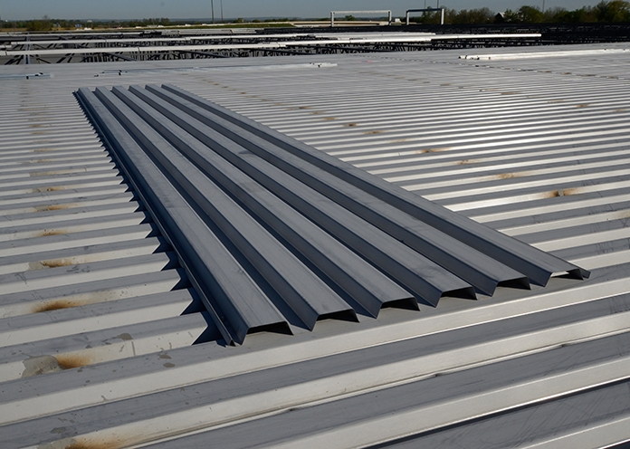
From the Agway 75 Series of high strength-to-weight roof decking, the RD75-300 profile is a 36” wide panel featuring 3” deep flutes, spaced 12” apart, providing the strength needed for heavier duty applications.
Our structural roof deck sections are available in a wide range of gauges in Galvanneal, galvanized or prepainted finishes: these options enable customers to determine the optimal combination of strength, performance, and affordability that best satisfies project-specific criteria. Agway roof deck sections are also available in an acoustic format with pre-punched holes in the webs of the deck which combine with acoustic batt insulation to significantly reduce ambient noise within a structure.
Bundled deck produced from either Galvanneal or G90 Galvanized coated steel is susceptible to storage stain when exposed to the elements. This staining is superficial only and is not a valid reason for rejection of this product.
For more information, refer to CSSBI Fact Sheet #33
Measurement Type
Profile Picture


1. Steel conforms to ASTM A653.
2. Section properties are in accordance with CSA-S136-07.
3. Values in row “S” are based on strength.
4. Values in row “D” are based on a deflection limit of 1/240 of the span.
5. Web crippling not included in strength values. See example calculation in notes to designer.
6. Contact the sales department for stocked colours and gauges.
7. The load table contained on this data sheet was prepared by Dr. R.M. Schuster P.Eng. Professor Emeritus of Structural Engineering, University of Waterloo, Ontario, Canada.
Specifications
| GAUGE | LENGTH | COVERAGE | ||
|---|---|---|---|---|
| MINIMUM | MAXIMUM | MINIMUM | MAXIMUM | |
| 22 | 16 | 48" | 600" | 36" |
| GAUGE | LENGTH | COVERAGE | ||
|---|---|---|---|---|
| MINIMUM | MAXIMUM | MINIMUM | MAXIMUM | |
| 22 | 16 | 1219.2 mm | 15.24 m | 914 mm |
Section Properties
| BASE STEEL THICKNESS |
WEIGHT G90 |
YIELD STRESS |
SECTION MODULUS |
DEFLECTION MOMENT OF INERTIA |
|
|---|---|---|---|---|---|
| in | psf | ksi | MID SPAN in 3 |
SUPPORT in 3 |
MID SPAN in 4 |
| 0.030 | 1.77 | 33 | 0.472 | 0.473 | 0.814 |
| 0.036 | 2.11 | 33 | 0.599 | 0.601 | 0.982 |
| 0.048 | 2.80 | 33 | 0.846 | 0.846 | 1.31 |
| 0.060 | 3.48 | 33 | 1.05 | 1.05 | 1.63 |
| BASE STEEL THICKNESS |
MASS Z275 |
YIELD STRESS |
SECTION MODULUS |
DEFLECTION MOMENT OF INERTIA |
|
|---|---|---|---|---|---|
| mm | kg/m | MPa | MID SPAN x10 3mm3 |
SUPPORT x10 3mm3 |
MID SPAN x10 3mm3 |
| 0.762 | 8.6 | 230 | 25.4 | 25.4 | 1.09 |
| 0.914 | 10.3 | 230 | 32.1 | 32.1 | 1.34 |
| 1.22 | 13.7 | 230 | 45.5 | 45.5 | 1.79 |
| 1.52 | 17.0 | 230 | 56.6 | 56.6 | 2.23 |
RD75-200 | RD75-200 CL
One of the Agway 75 Series of high strength-to-weight roof decking, the RD75-200 profile is a 32” wide panel featuring 3” deep flutes, spaced 8” apart, providing the strength needed for heavier duty applications.
Our structural roof deck sections are available in a wide range of gauges in Galvanneal, galvanized or prepainted finishes: these options enable customers to determine the optimal combination of strength, performance, and affordability that best satisfies project-specific criteria. Agway roof deck sections are also available in an acoustic format with pre-punched holes in the webs of the deck which combine with acoustic batt insulation to significantly reduce ambient noise within a structure.
Bundled deck produced from either Galvanneal or G90 Galvanized coated steel is susceptible to storage stain when exposed to the elements. This staining is superficial only and is not a valid reason for rejection of this product.
Measurement Type
Profile Picture


1. Steel conforms to ASTM A653.
2. Section properties are in accordance with CSA-S136-07.
3. Values in row “S” are based on strength.
4. Values in row “D” are based on a deflection limit of 1/240 of the span.
5. Web crippling not included in strength values. See example calculation in notes to designer.
6. Contact the sales department for stocked colours and gauges.
7. The load table contained on this data sheet was prepared by Dr. R.M. Schuster P.Eng. Professor Emeritus of Structural Engineering, University of Waterloo, Ontario, Canada.


1. Steel conforms to ASTM A653.
2. Section properties are in accordance with CSA-S136-07.
3. Values in row “S” are based on strength.
4. Values in row “D” are based on a deflection limit of 1/240 of the span.
5. Web crippling not included in strength values. See example calculation in notes to designer.
6. Contact the sales department for stocked colours and gauges.
7. The load table contained on this data sheet was prepared by Dr. R.M. Schuster P.Eng. Professor Emeritus of Structural Engineering, University of Waterloo, Ontario, Canada.
Specifications
| GAUGE | LENGTH | COVERAGE | ||
|---|---|---|---|---|
| MINIMUM | MAXIMUM | MINIMUM | MAXIMUM | |
| 22 | 16 | 48" | 600" | 32" |
| GAUGE | LENGTH | COVERAGE | ||
|---|---|---|---|---|
| MINIMUM | MAXIMUM | MINIMUM | MAXIMUM | |
| 22 | 16 | 1219.2 mm | 15.24 m | 813 mm |
Section Properties
| BASE STEEL THICKNESS |
WEIGHT G90 |
YIELD STRESS |
SECTION MODULUS |
DEFLECTION MOMENT OF INERTIA |
|
|---|---|---|---|---|---|
| in | psf | ksi | MID SPAN in 3 |
SUPPORT in 3 |
MID SPAN in 4 |
| 0.030 | 2.08 | 33 | 0.375 | 0.397 | 0.677 |
| 0.036 | 2.48 | 33 | 0.485 | 0.503 | 0.880 |
| 0.048 | 3.29 | 33 | 0.675 | 0.724 | 1.27 |
| 0.060 | 4.10 | 33 | 0.862 | 0.904 | 1.64 |
| BASE STEEL THICKNESS |
MASS Z275 |
YIELD STRESS |
SECTION MODULUS |
DEFLECTION MOMENT OF INERTIA |
|
|---|---|---|---|---|---|
| mm | kg/m | MPa | MID SPAN x10 3mm3 |
SUPPORT x10 3mm3 |
MID SPAN x10 3mm3 |
| 0.762 | 10.1 | 230 | 20.1 | 21.3 | 0.922 |
| 0.914 | 12.1 | 230 | 26.0 | 27.0 | 1.20 |
| 1.22 | 16.1 | 230 | 36.2 | 38.8 | 1.73 |
| 1.52 | 20.0 | 230 | 46.3 | 48.6 | 2.24 |
RD75-150 | RD75-150 CL
Agway’s 75 series roof deck panels offer the highest strength-to-weight ratios available; the RD75-150 profile is a 24” wide panel featuring 3” deep flutes, spaced 6” apart, resulting in our strongest roof deck offering.
Our structural roof deck sections are available in a wide range of gauges in Galvanneal, galvanized or prepainted finishes: these options enable customers to determine the optimal combination of strength, performance, and affordability that best satisfies project-specific criteria. Agway roof deck sections are also available in an acoustic format with pre-punched holes in the webs of the deck which combine with acoustic batt insulation to significantly reduce ambient noise within a structure.
Bundled deck produced from either Galvanneal or G90 Galvanized coated steel is susceptible to storage stain when exposed to the elements. This staining is superficial only and is not a valid reason for rejection of this product.
For more information, refer to CSSBI Fact Sheet #33
Measurement Type
Profile Picture


1. Steel conforms to ASTM A653.
2. Section properties are in accordance with CSA-S136-07.
3. Values in row “S” are based on strength.
4. Values in row “D” are based on a deflection limit of 1/240 of the span.
5. Web crippling not included in strength values. See example calculation in notes to designer.
6. Contact the sales department for stocked colours and gauges.
7. The load table contained on this data sheet was prepared by Dr. R.M. Schuster P.Eng. Professor Emeritus of Structural Engineering, University of Waterloo, Ontario, Canada.


1. Steel conforms to ASTM A653.
2. Section properties are in accordance with CSA-S136-07.
3. Values in row “S” are based on strength.
4. Values in row “D” are based on a deflection limit of 1/240 of the span.
5. Web crippling not included in strength values. See example calculation in notes to designer.
6. Contact the sales department for stocked colours and gauges.
7. The load table contained on this data sheet was prepared by Dr. R.M. Schuster P.Eng. Professor Emeritus of Structural Engineering, University of Waterloo, Ontario, Canada.
Specifications
| GAUGE | LENGTH | COVERAGE | ||
|---|---|---|---|---|
| MINIMUM | MAXIMUM | MINIMUM | MAXIMUM | |
| 22 | 16 | 48" | 600" | 24" |
| GAUGE | LENGTH | COVERAGE | ||
|---|---|---|---|---|
| MINIMUM | MAXIMUM | MINIMUM | MAXIMUM | |
| 22 | 16 | 1219.2 mm | 15.24 m | 610 mm |
Section Properties
| BASE STEEL THICKNESS |
WEIGHT G90 |
YIELD STRESS |
SECTION MODULUS |
DEFLECTION MOMENT OF INERTIA |
|
|---|---|---|---|---|---|
| in | psf | ksi | MID SPAN in 3 |
SUPPORT in 3 |
MID SPAN in 4 |
| 0.030 | 2.34 | 33 | 0.485 | 0.492 | 0.866 |
| 0.036 | 2.80 | 33 | 0.621 | 0.624 | 1.07 |
| 0.048 | 3.71 | 33 | 0.882 | 0.898 | 1.46 |
| 0.060 | 4.63 | 33 | 1.12 | 1.12 | 1.82 |
| BASE STEEL THICKNESS |
MASS Z275 |
YIELD STRESS |
SECTION MODULUS |
DEFLECTION MOMENT OF INERTIA |
|
|---|---|---|---|---|---|
| mm | kg/m | MPa | MID SPAN x10 3mm3 |
SUPPORT x10 3mm3 |
MID SPAN x10 3mm3 |
| 0.762 | 11.7 | 230 | 26.0 | 26.4 | 1.18 |
| 0.914 | 13.7 | 230 | 33.3 | 33.4 | 1.46 |
| 1.22 | 18.1 | 230 | 47.4 | 48.2 | 2.00 |
| 1.52 | 22.6 | 230 | 60.0 | 60.3 | 2.49 |
RD36 | RD36 CL
The RD36 profile is Agway’s most popular roof deck section and is the preferred deck section for industrial/commercial applications.
Our structural roof deck sections are available in a wide range of gauges in Galvanneal, galvanized or prepainted finishes: these options enable customers to determine the optimal combination of strength, performance, and affordability that best satisfies project-specific criteria. Agway roof deck sections are also available in an acoustic format with pre-punched holes in the webs of the deck which combine with acoustic batt insulation to significantly reduce ambient noise within a structure.
Bundled deck produced from either Galvanneal or G90 Galvanized coated steel is susceptible to storage stain when exposed to the elements. This staining is superficial only and is not a valid reason for rejection of this product.
For more information, refer to CSSBI Fact Sheet #33
Measurement Type
Profile Picture


1. Steel conforms to ASTM A653.
2. Section properties are in accordance with CSA-S136-07.
3. Values in row “S” are based on strength.
4. Values in row “D” are based on a deflection limit of 1/240 of the span.
5. Web crippling not included in strength values. See example calculation in notes to designer.
6. Contact the sales department for stocked colours and gauges.
7. The load table contained on this data sheet was prepared by Dr. R.M. Schuster P.Eng. Professor Emeritus of Structural Engineering, University of Waterloo, Ontario, Canada.


1. Steel conforms to ASTM A653.
2. Section properties are in accordance with CSA-S136-07.
3. Values in row “S” are based on strength.
4. Values in row “D” are based on a deflection limit of 1/240 of the span.
5. Web crippling not included in strength values. See example calculation in notes to designer.
6. Contact the sales department for stocked colours and gauges.
7. The load table contained on this data sheet was prepared by Dr. R.M. Schuster P.Eng. Professor Emeritus of Structural Engineering, University of Waterloo, Ontario, Canada.
Specifications
| GAUGE | LENGTH | COVERAGE | ||
|---|---|---|---|---|
| MINIMUM | MAXIMUM | MINIMUM | MAXIMUM | |
| 22 | 16 | 36" | 540" | 36" |
| GAUGE | LENGTH | COVERAGE | ||
|---|---|---|---|---|
| MINIMUM | MAXIMUM | MINIMUM | MAXIMUM | |
| 22 | 16 | 914 mm | 13.72 m | 914 mm |
Section Properties
| BASE STEEL THICKNESS |
WEIGHT G90 |
YIELD STRESS |
SECTION MODULUS |
DEFLECTION MOMENT OF INERTIA |
|
|---|---|---|---|---|---|
| in | psf | ksi | MID SPAN in 3 |
SUPPORT in 3 |
MID SPAN in 4 |
| 0.030 | 1.69 | 33 | 0.184 | 0.194 | 0.163 |
| 0.036 | 2.02 | 33 | 0.226 | 0.233 | 0.204 |
| 0.048 | 2.68 | 33 | 0.307 | 0.315 | 0.208 |
| 0.060 | 3.33 | 33 | 0.387 | 0.389 | 0.349 |
| BASE STEEL THICKNESS |
MASS Z275 |
YIELD STRESS |
SECTION MODULUS |
DEFLECTION MOMENT OF INERTIA |
|
|---|---|---|---|---|---|
| mm | kg/m | MPa | MID SPAN x10 3mm3 |
SUPPORT x10 3mm3 |
MID SPAN x10 3mm3 |
| 0.762 | 8.27 | 230 | 9.89 | 10.4 | 0.223 |
| 0.914 | 9.86 | 230 | 12.1 | 12.5 | 0.278 |
| 1.22 | 13.1 | 230 | 16.5 | 16.9 | 0.382 |
| 1.52 | 16.3 | 230 | 20.8 | 20.9 | 0.476 |
Flat Lock Panels
Flat Panel Size
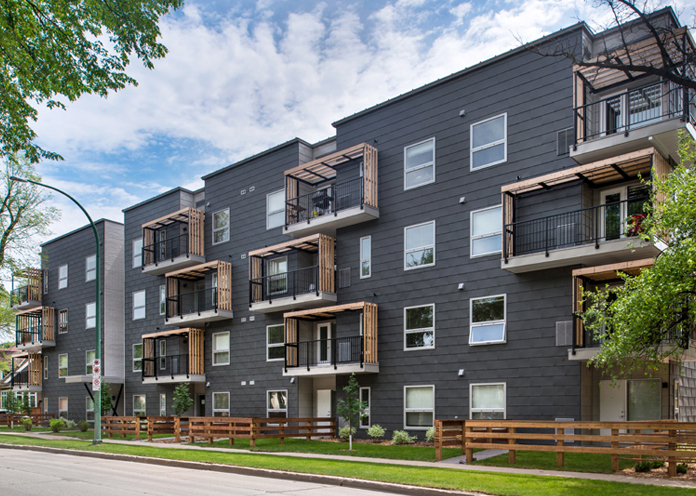
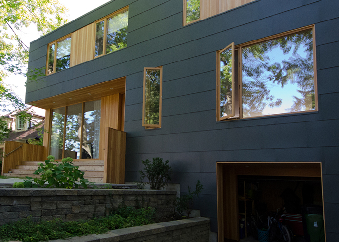
Flat Lock Panels are available in standard sizes with a horizontal coverage of 36” (914 mm) and a vertical coverage of 16” (406 mm) allowing for a 1” (25 mm) hem. The actual coverage area would be 33” x 13” (838 mm x 76 mm).
Flat Panel Weight
Flat Lock panels are available in 26 and 24 gauge.
Available Material
Rheinzink, Plain or Prepainted Steel, Indaten, aluminum and copper.
Available Colours
With a choice of over 40 stock and special colours available including the Perspectra Plus Series, KYNAR 500 and the GraniteDeep Mat colours you have a wide variety of colour and design options available to you.
Measurement Type
Plain Finishes
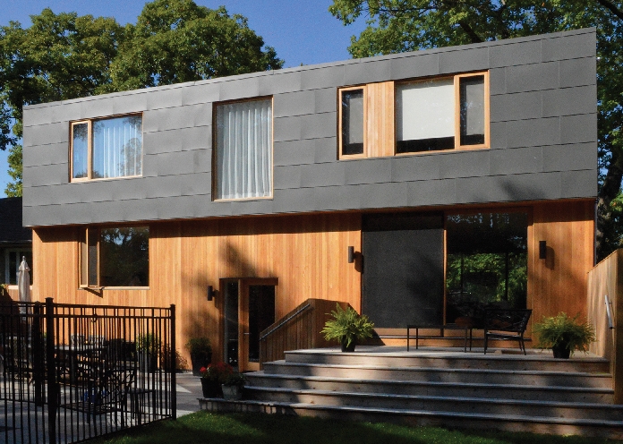
Architects and Specification Writers are increasingly selecting unpainted metallic coated steels for architectural roofing and cladding applications on building exteriors where they want a “Silver” metallic finish.
Resources
Galvanized
The principle reason for Galvanizing is to protect the steel from corrosion. Galvanized coating is essentially pure zinc. Cold rolled steel is dipped into a bath of molten zinc (hence the name Hot-dipped Galvanized). The coating weight is controlled by “air knives” which adjust to produce the desired coating.
The coating thickness chosen will have a direct impact on the life of the material. Agway uses G90 (imperial) or Z275 (metric) coating weight to insure a long life for the product. G90 Coating contributes about 1.6 mils (0.0016 inches) of thickness to the final coated sheet (or 0.0008 inches of zinc to each side of the material).
Zinc provides outstanding anti-corrosion performance for the steel substrate due to a slow oxidation rate and protective sacrificial action, which inhibits corrosion of the steel. The material is passivated and left “dry” or un-oiled. This passivation process provides increased protection to the coating by immersing the material in an acid solution which removes any “free iron” contamination. This contamination can result in premature corrosion of the material. Another result of passivation is the formation of a transparent oxide film that also protects the material from corrosion. The material is then temper rolled to insure a smooth surface.
Galvanized steel conforms to the general requirements of ASTM A-653/653M
Galvanneal / LZC / Satin coat /Wipe coat
After the galvanizing process and while the zinc is still in liquid form, the steel is annealed by passing the material through a furnace. Once the material is annealed, the coating becomes an iron-zinc alloy rather than a free zinc coating as in Galvanized material. This process provides a smoother matt finish, which improves adhesion for painted applications. Many Galvanneal products are painted after fabrication. Galvanneal material offers more corrosion resistance then cold rolled material, and improved spot-weldability over Galvanized material. The baked zinc coating on Galvanneal material is harder than Galvanized material, which makes it extremely scratchresistant. Agway uses ZF75 Coating weight to insure a long life of the product. The cost of Galvanneal material is less then Galvanized material.
Galvanneal material conforms to the general requirements of ASTM A-653/653M
Galvalume Plus®
Galvalume material has approximately 55% aluminum and 45% zinc coating placed onto the steel strip by the hot dip process. The coating is chemically bonded to the steel and has a clear organic resin coating over the aluminum and zinc. This resin is applied to both sides of the material and is then thermally cured. This coating has a high resistance to storage stain. Galvalume material has at least twice the corrosion resistance of Galvanized material with the same coating thickness. Galvalume Plus is ideal for unpainted roofing and siding, the surface is bright with a fine spangle, and has a high heat reflctivity. However, the end user should be aware that plain Galvalume material may display some variations in aesthetic finish quality and a high degree of consistency cannot be guaranteed. There is no need for chemical treatments or vanishing oil; this helps to minimize fingerprints when handling. Agway uses AZ50 (imperial) or AZM150 (metric) for the coating weight to insure a long life of the product.
Galvalume® material conforms to the general requirements of ASTM A792/792M

