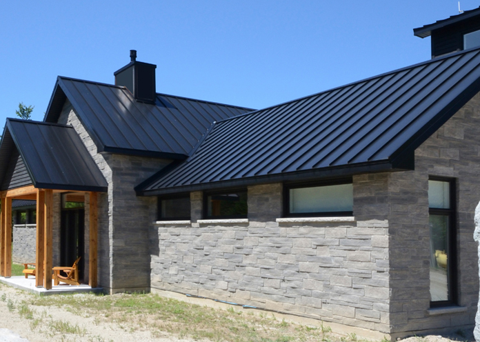
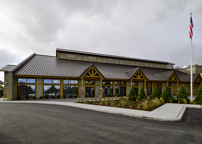
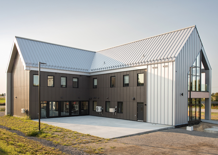
Eavestroughs & Accessories
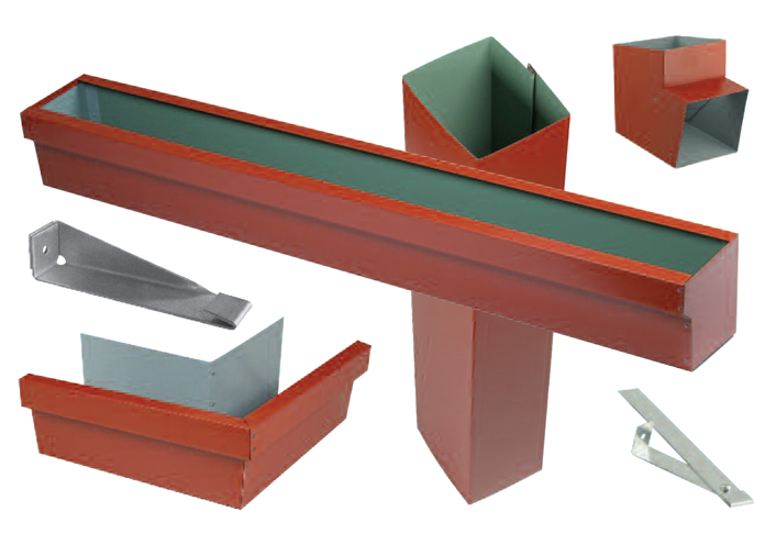
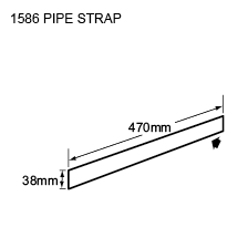
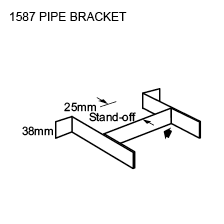
From Downspout to Pipe Straps, Agway has everything you’ll ever need for your metal roofing project.. In addition to our standard flashings, available in a full range of gauges, we also offer our 1500 Series Eavestroughs and Accessories, designed specifically for metal roof projects.
Measurement Type
Profile Picture
Features
- Available in 22, 24 and 26 ga.
- Prepainted and Galvanized steel
- Aluminum, Copper, Stainless Steel, Indaten™ and Zinc
- Custom sizes available on request
- Available in 10’-0”, 16’-3” and 20’-2” lengths
Note:
Swaging is available on request for overlap on Gutter but is not provided as a standard
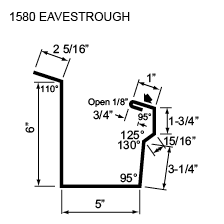
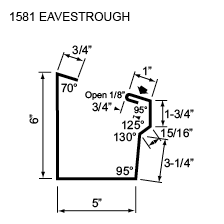
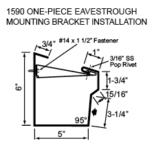
1500 Series Eavestrough Accessories
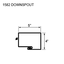
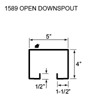
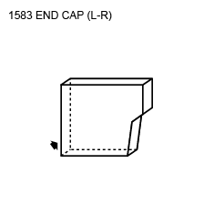
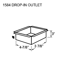
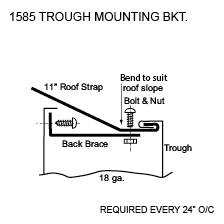
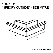
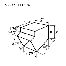
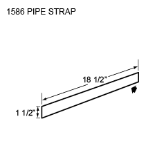
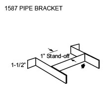
Features
- Available in 22, 24 and 26 ga.
- Prepainted and Galvanized steel
- Aluminum, Copper, Stainless Steel, Indaten™ and Zinc
- Custom sizes available on request
- Available in 3.1m, 5m and 6.2m lengths
Note:
Swaging is available on request for overlap on Gutter but is not provided as a standard
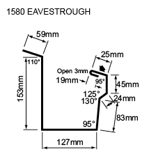
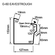
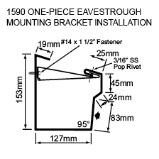
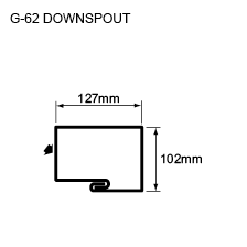
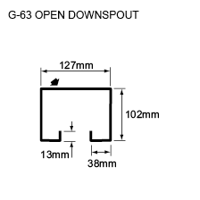
1500 Series Eavestrough Accessories

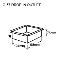
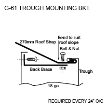
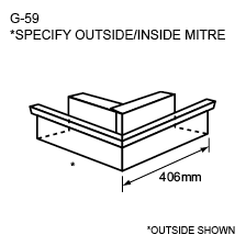
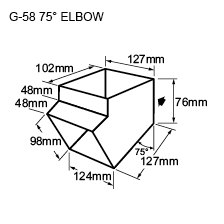
SnoBars
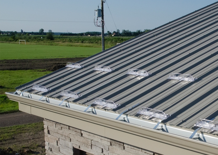
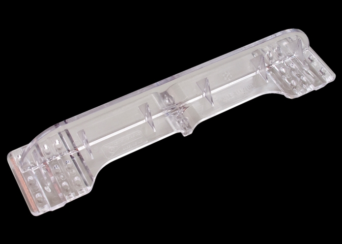
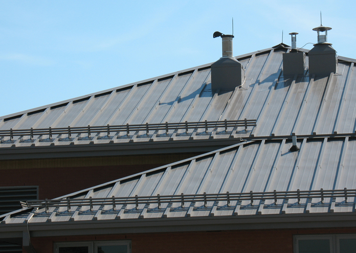
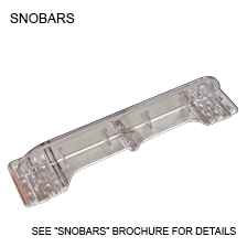
Agway now offers SnoBars, a custom Snow Control System to keep doorways safe. SnoBars are manufactured from transparent polycarbonate, to let all the vibrant colour and aesthetic beauty of your roof show through, while adding a professional finish.
Features & Benefits
- Innovative design offers control of snow to deter avalanches above doorways and other high traffic areas
- Can be used with Agway’s Century Rib or Optimum Rib profiles
- Manufactured from UV-stabilized polycarbonate
- Clear polycarbonate allows roof colour to show through
- Width of SnoBar offers snow control over 13”
- Easy to install
Installation
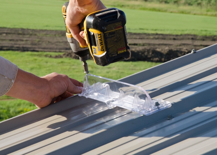
- Position the SnoBars onto the ribs of the roof sheet over the area of the roof that requires snow control and fasten with appropriate fasteners through the high rib of the profile. Use a minimum of four (4) Woodgrip fasteners per SnoBar with a minimum of 3/4” penetration into the wood substrate below the metal roofing.
- It is recommended that clear caulking is applied to the bearing area of the SnoBar before setting it in place on the profile and before fastening with screws.
- For more effective snow control, stagger the SnoBars both vertically and horizontally on the roof.
Notes
SnoBars placement will vary from region to region and will be influenced by roof pitch, length of run and spacing between seams. Local custom may be the best guide as to placement, and additional recommendations can be found in SMACNA and other industry standards.
Placement should be determined by a qualified design professional.
Snow Control Systems sold by Agway Metals Inc. are not to be used as a fall protection system. The Buyer agrees that under no circumstances shall the Seller be liable for any consequential, special or indirect damages.
Measurement Type
Sno Gem
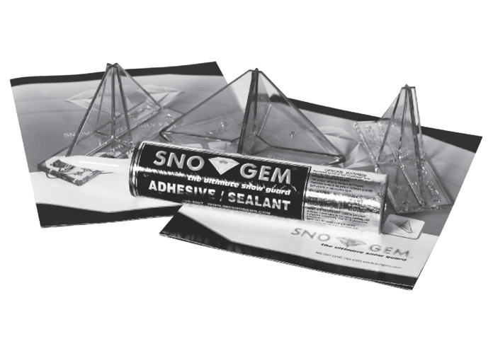
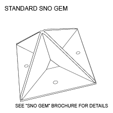
Our Sno-Gem Snow Guard System now offers Agway customers an innovative snow control system with incredible strength. And, because it is manufactured from clear polycarbonate, its visual transparency enables the Sno-Gem Snow Guard to aesthetically integrate with other components and deliver a very pleasing and professionally finished appearance.
Features
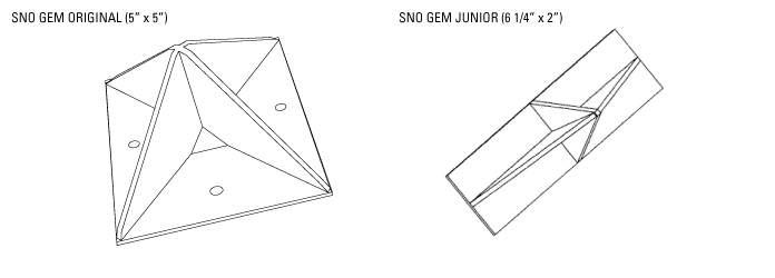
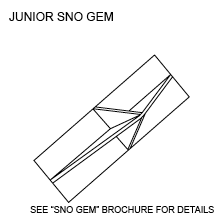
- Sno Gem: Original (5” x 5”) and Junior (6 1/4” x 2”) profiles and adhesive
- Manufactured from UV-stabilized polycarbonate
- Innovative design offers the largest base in the industry (25 sq. ins), providing the greatest shear strength
- Clear polycarbonate allows the roof colour to show through
- Two appearance options, permitting a horizontal or vertical look
- Horizontal application offers a 5” barrier
- Rotating the Sno-Gem 45° offers 7” of protection (40% more coverage, useful on wider panels)
Notes
- A double row is recommended over walkways and building entrances
- Spacing of Sno-Gems will depend on roof pitch, width and length of panels
- Junior Sno-Gem is adaptable to Century Rib Roofing Profile
- Colour matching is available (200 pc. minimum). Call for information.
- See over for Sno-Gem installation instructions
Sno Gem Installation Instructions
Sno-Gem Snow Guards offer a state-of-the-art application technique using 3M VHB Tape. With proper installation, immediate adhesion upon application is 50%. This method is fully cured in 72 hours, upon which you can expect up to 1,300 lbs. of shear strength per unit. When compared with other application methods, you can also expect reduced installation times and cost savings. This method is for flat panel installation only. Temperature must be above freezing at time of installation.
3M Adhesive Tape Installation: Apply a thin coat of #94 primer to the roof surface. Peel release paper backing off adhesive tape on Sno-Gem base. Place Sno-Gem in position on metal surface, applying firm, even pressure perpendicular to the roof surface. Apply a bead of sealant around the perimeter of the base.
Sno-Gem also offers two additional application methods; on-site application of adhesive and the use of mechanical fasteners. Whichever method you choose, you will benefit from Sno-Gem’s proven design, appearance and long life.
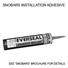
Adhesive Attachment: Where adhesive is to be the sole means of attaching the Sno-Gem Snow Guard to the roof surface, Sno-Gem currently recommends the use of Surebond SB-190 Everseal Sealant Caulk. This product has a proven record for this particular use and is well known in the metal roofing industry. To install Sno-Gem Snow Guards, contact surfaces shall be wiped only with Isopropyl Alcohol and the adhesive shall be applied so as to completely coat the underside of the device before positioning it on the roof surface. After positioning, exert uniform pressure until adhesive is squeezed out around the entire perimeter of the Sno-Gem and point up the joint to create a bead that is free of gaps or air pockets. It should be noted that under certain conditions, temporary measures may need to be employed to hold the Sno-Gem in place until the initial set of the adhesive has taken place, and that the total cure requires 28 days of at least 10°C (50°F). Clean up using Mineral Spirits or Naptha gas.
Mechanical Attachment: Where temperatures will not be suitable for adhesive installation or where additional strength is required, Sno-Gem Snow Guards may be attached with through fasteners in combination with the adhesive or a high-quality silicone/sealant where conditions permit. Sno-Gem Snow Guards are provided with four starter dimples: begin by drilling a 7/32” clearance hole to accommodate a #10 Type A self-tapping fastener (flat or oval head). Fastener selection should be governed by substrate and anticipated loads, but stainless steel or corrosion resistant fasteners should be insisted upon. Adhesive or sealant should be applied so as to completely coat the underside of the device before positioning it on the roof surface. Sufficient compression should be applied to squeeze adhesive/ sealant out around the perimeter of the base and a bead of the same material applied to create a waterproof joint free of gaps and air pockets.
Notes
Sno-Gem Snow Guard placement will vary from region to region and will be influenced by roof pitch, length of run and spacing between seams. Local custom may be the best guide as to placement, and additional recommendations can be found in SMACNA and other industry standards. Placement should be determined by a qualified design professional.
Snow Control Systems sold by Agway Metals Inc. are not to be used as a fall protection system. The Buyer agrees that under no circumstances shall the Seller be liable for any consequential, special or indirect damages.
Measurement Type
Standard Flashings MR
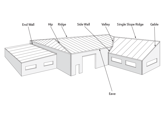
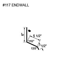
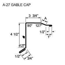
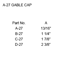
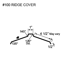
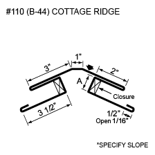
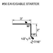
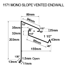
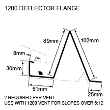
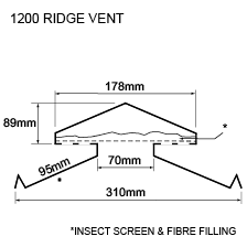
In terms of flashings and trims, Agway offers everything needed to complete your Metal Roof project. From Eaves and Gables, to Vents and Ridges, Agway has it all. Should your project require anything different or unique, custom flashings can also be accommodated.
Measurement Type
Profile Picture
PROFILE LIST


Typical Flashings
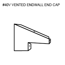
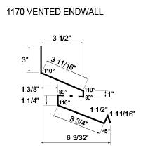
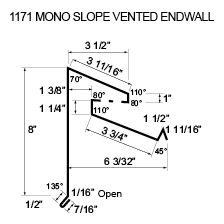
ENDWALLS
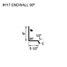
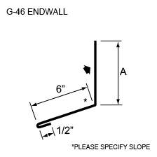
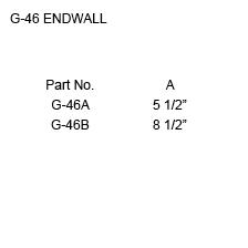
FLASHINGS
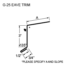
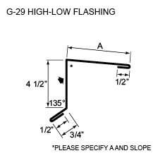
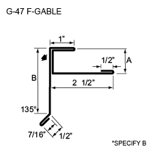
GABLES
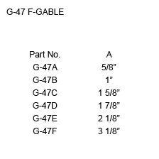
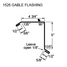
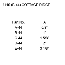
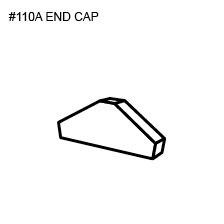
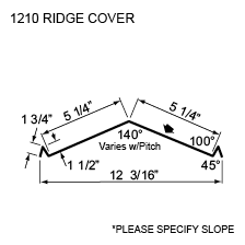
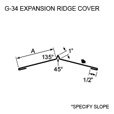
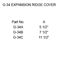
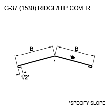
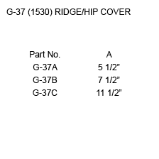
RIDGES
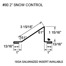
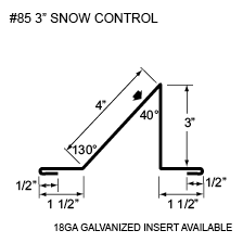
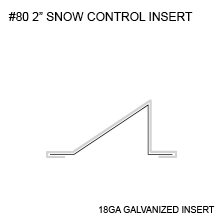
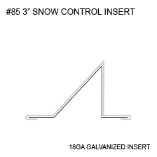
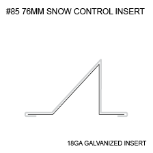
SNOW CONTROL
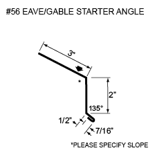
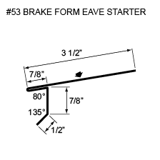
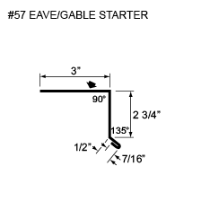
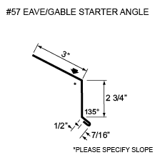
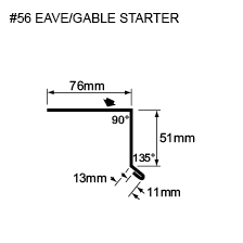
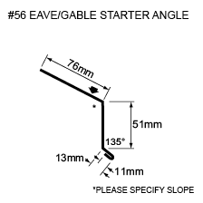
EAVE AND GABLE STARTERS
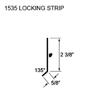
TOP CLOSURES
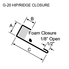
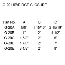
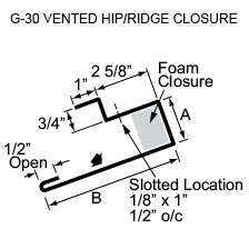
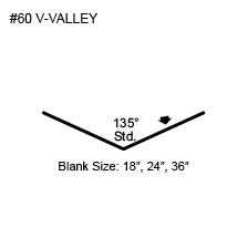
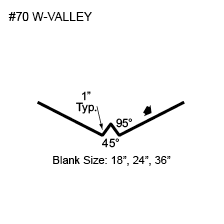
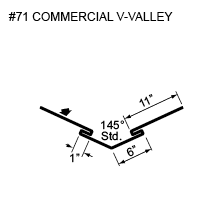
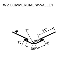
VALLEYS
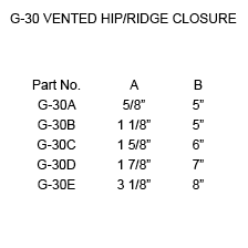
RIDGE VENTS
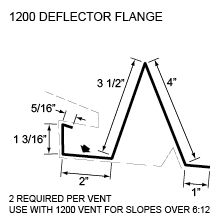
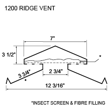
PROFILE LIST


Typical Flashings
ENDWALLS
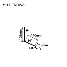
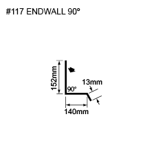
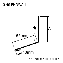
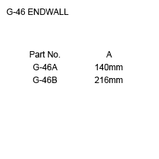
FLASHINGS
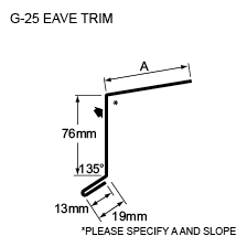
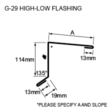
GABLES
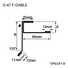
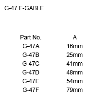
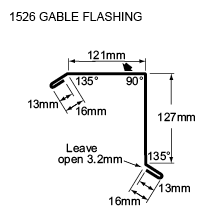
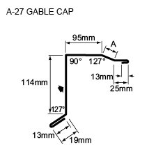
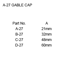
RIDGES
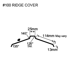
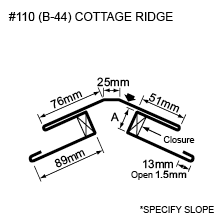
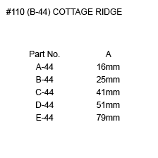

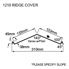
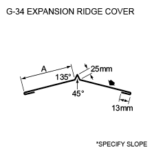
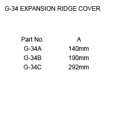
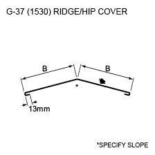
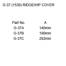
SNOW CONTROL
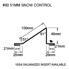
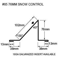
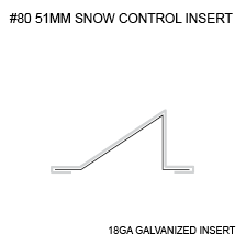


EAVE AND GABLE STARTERS
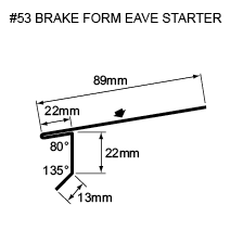
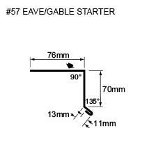
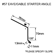
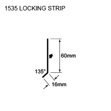
TOP CLOSURES
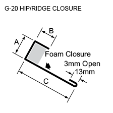
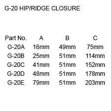
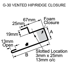
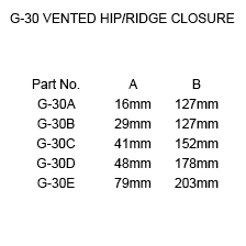
VALLEYS
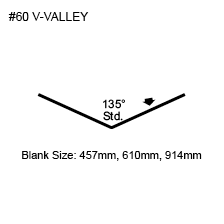
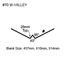
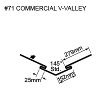
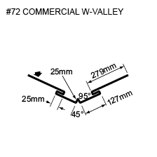
RIDGE VENTS

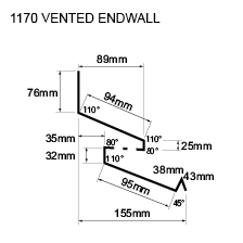
Batten Profiles
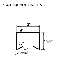
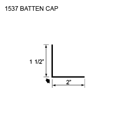
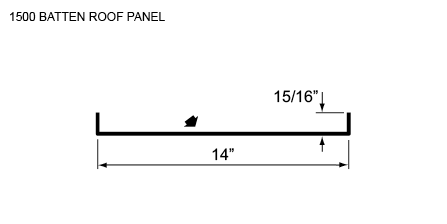
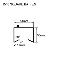
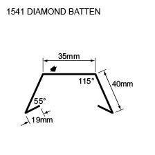
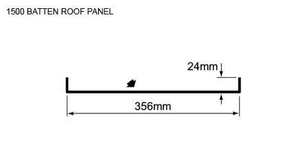
Agway offers two unique Batten Profiles – Board and Batten and Diamond Batten – in variable widths and lengths up to 20’. These profiles are ideal for both wall and roof applications, and are available in Pre-painted Steel, Aluminum, Copper, Stainless Steel, or Zinc.
Measurement Type
Profile Picture


Board & Batten
- Custom lengths from 1′ – 0″ to 20′ – 2″
- Prepainted Steel, Aluminum, Copper, Stainless Steel and Zinc
- Available with a starter cleat and 90° end bend
- Can be notched and preformed for knee-bend applications
- Suitable for Roof and Wall applications
- Custom dimensioning also available
- All installations must be on a solid decking c/w moisture barrier
Diamond Batten
- Custom lengths from 1′ – 0″ to 20′ – 2″
- Prepainted Steel, Aluminum, Copper, Stainless Steel and Zinc
- Available with a starter cleat and 90° end bend
- Can be notched and preformed for knee-bend applications
- Custom dimensions also available
- Suitable for Roof or Wall applications
- All installations must be on a solid decking c/w moisture barrier
Flashings and Trims
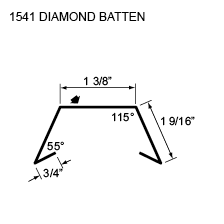
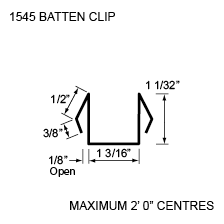
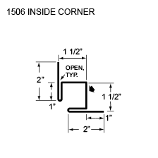
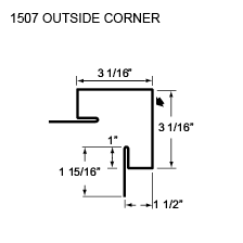
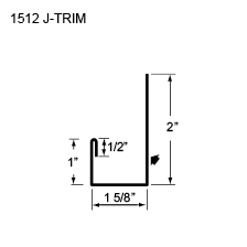
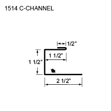
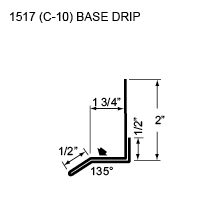

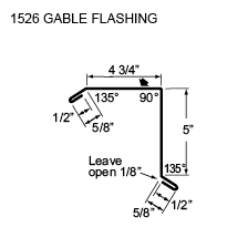
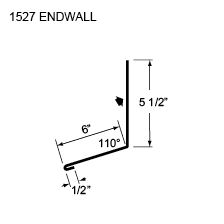

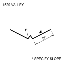
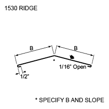
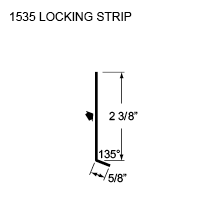


Board & Batten
- Custom lengths from 305 mm to 6.7 m
- Prepainted Steel, Aluminum, Copper, Stainless Steel and Zinc
- Available with a starter cleat and 90° end bend
- Can be notched and performed for knee-bend applications
- Suitable for Roof and Wall applications
- Custom dimensioning also available
- All installations must be on a solid decking c/w moisture barrier
Diamond Batten
- Custom lengths from 305 mm to 6.7 m
- Prepainted Steel, Aluminum, Copper, Stainless Steel and Zinc
- Available with a starter cleat and 90° end bend
- Can be notched and performed for knee-bend applications
- Custom dimensions also available
- Suitable for Roof or Wall applications
- All installations must be on a solid decking c/w moisture barrier
Flashings and Trims
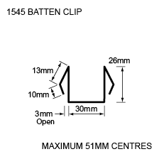
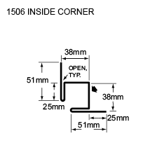
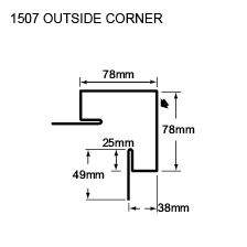
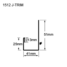
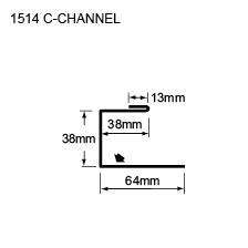
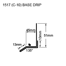

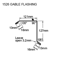
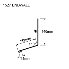

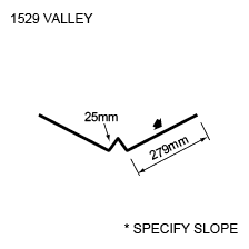
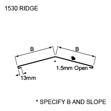
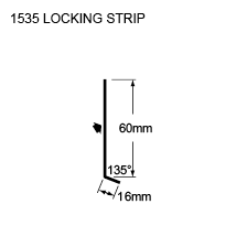
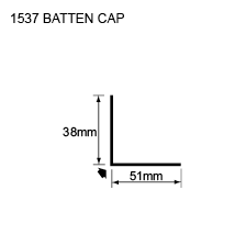
Diamond Rib
Available in 30 gauge to 24 gauge, Agway’s extremely popular and versatile Diamond Rib profile can be used as wall and roofing cladding or interior liner panels, as well as accent striping with other as well as other contiguous profiles. Diamond Rib is ideal for agricultural, industrial or commercial applications.
Measurement Type
Profile Picture

1. Steel conforms to ASTM A653.
2. Section properties are in accordance with CSA-S136-07.
3. Values in row “S” are based on strength.
4. Values in row “D” are based on a deflection limit of 1/180 of the span.
5. Web crippling not included in strength values. See example calculation in notes to designer.
6. Contact the sales department for stocked colours and gauges.
7. The load table contained on this data sheet was prepared by Dr. R.M. Schuster P.Eng. Professor Emeritus of Structural Engineering, University of Waterloo, Ontario, Canada.
Specifications
| GAUGE | LENGTH | COVERAGE | ||
|---|---|---|---|---|
| MINIMUM | MAXIMUM | MINIMUM | MAXIMUM | |
| 30 | 24 | 16 | 540 | 36 |
| 30 | 22 | 16 | 480 | 30 |
| GAUGE | LENGTH | COVERAGE | ||
|---|---|---|---|---|
| MINIMUM | MAXIMUM | MINIMUM | MAXIMUM | |
| 30 | 24 | 406 | 13.72 | 914 |
| 30 | 22 | 406 | 12.92 | 780 |
Section Properties
| BASE STEEL THICKNESS |
WEIGHT G90 |
YIELD STRESS |
SECTION MODULUS |
DEFLECTION MOMENT OF INERTIA |
|
|---|---|---|---|---|---|
| in | psf | ksi | MID SPAN in 3 |
SUPPORT in 3 |
MID SPAN in 4 |
| 0.0120 | 0.64 | 33 | 0.0221 | 0.0202 | 0.0144 |
| 0.0135 | 0.71 | 80 | 0.0227 | 0.0203 | 0.0152 |
| 0.0180 | 0.93 | 33 | 0.0381 | 0.0361 | 0.0227 |
| 0.0240 | 1.22 | 33 | 0.0550 | 0.0498 | 0.0302 |
| 0.0300 | 1.51 | 33 | 0.0683 | 0.0637 | 0.0376 |
| BASE STEEL THICKNESS |
MASS Z275 |
YIELD STRESS |
SECTION MODULUS |
DEFLECTION MOMENT OF INERTIA |
|
|---|---|---|---|---|---|
| mm | kg/m | MPa | MID SPAN x10 3mm3 |
SUPPORT x10 3mm3 |
MID SPAN x10 3mm3 |
| 0.305 | 3.11 | 230 | 1.19 | 1.09 | 0.0196 |
| 0.343 | 3.46 | 550 | 1.22 | 1.09 | 0.0207 |
| 0.457 | 4.52 | 230 | 2.04 | 1.94 | 0.0309 |
| 0.610 | 5.94 | 230 | 2.96 | 2.68 | 0.0412 |
| 0.762 | 7.36 | 230 | 3.67 | 3.42 | 0.0514 |
4-150
An exposed fastener system, the 4-150 profile demonstrates the versatility of Agway profile designs as it can be used as a roof or wall cladding. Moreover, its load bearing capabilities enable the 4-150 profile to function as a structural member. An economical system that’s easy to install, 4-150 is a popular choice for agricultural, industrial and commercial applications.
Agway’s 4-150 comes in a full range of stock colours, with colour matched fasteners, trims and accessories.
Measurement Type
Profile Picture

1. Steel conforms to ASTM A653.
2. Section properties are in accordance with CSA-S136-07.
3. Values in row “S” are based on strength.
4. Values in row “D” are based on a deflection limit of 1/180 of the span.
5. Web crippling not included in strength values. See example calculation in notes to designer.
6. Contact the sales department for stocked colours and gauges.
7. The load table contained on this data sheet was prepared by Dr. R.M. Schuster P.Eng. Professor Emeritus of Structural Engineering, University of Waterloo, Ontario, Canada.

1. Steel conforms to ASTM A653.
2. Section properties are in accordance with CSA-S136-07.
3. Values in row “S” are based on strength.
4. Values in row “D” are based on a deflection limit of 1/180 of the span.
5. Web crippling not included in strength values. See example calculation in notes to designer.
6. Contact the sales department for stocked colours and gauges.
7. The load table contained on this data sheet was prepared by Dr. R.M. Schuster P.Eng. Professor Emeritus of Structural Engineering, University of Waterloo, Ontario, Canada.
Specifications
| GAUGE | LENGTH | COVERAGE | ||
|---|---|---|---|---|
| MINIMUM | MAXIMUM | MINIMUM | MAXIMUM | |
| 29 | 22 | 10 | 828 | 36 |
| GAUGE | LENGTH | COVERAGE | ||
|---|---|---|---|---|
| MINIMUM | MAXIMUM | MINIMUM | MAXIMUM | |
| 29 | 22 | 254 | 21.03 | 914 |
Section Properties
| BASE STEEL THICKNESS |
WEIGHT G90 |
YIELD STRESS |
SECTION MODULUS |
DEFLECTION MOMENT OF INERTIA |
|
|---|---|---|---|---|---|
| in | psf | ksi | MID SPAN in 3 |
SUPPORT in 3 |
MID SPAN in 4 |
| 0.0135 | 0.73 | 80 | 0.0340 | 0.0278 | 0.0455 |
| 0.0150 | 0.80 | 33 | 0.0428 | 0.0364 | 0.0564 |
| 0.0180 | 0.95 | 50 | 0.0509 | 0.0432 | 0.0673 |
| 0.0240 | 1.25 | 33 | 0.0777 | 0.0674 | 0.0938 |
| 0.0300 | 1.55 | 33 | 0.101 | 0.0867 | 0.117 |
| BASE STEEL THICKNESS |
MASS Z275 |
YIELD STRESS |
SECTION MODULUS |
DEFLECTION MOMENT OF INERTIA |
|
|---|---|---|---|---|---|
| mm | kg/m | MPa | MID SPAN x10 3mm3 |
SUPPORT x10 3mm3 |
MID SPAN x10 3mm3 |
| 0.343 | 3.55 | 550 | 1.83 | 1.49 | 0.0621 |
| 0.381 | 3.91 | 230 | 2.30 | 1.95 | 0.0769 |
| 0.457 | 4.64 | 345 | 2.74 | 2.32 | 0.0919 |
| 0.610 | 6.09 | 230 | 4.17 | 3.62 | 0.128 |
| 0.762 | 7.54 | 230 | 5.45 | 4.66 | 0.160 |
Century Rib
Economical and easy-to-install, Agway’s Century Rib profile is our most popular product for agricultural roof applications. Available in a wide range of colours, Agway’s Century Rib profile, combined with available trims, vents, fasteners and other accessories, provides a complete roofing solution for any project.
Measurement Type
Profile Picture

1. Steel conforms to ASTM A653.
2. Section properties are in accordance with CSA-S136-07.
3. Values in row “S” are based on strength.
4. Values in row “D” are based on a deflection limit of 1/180 of the span.
5. Web crippling not included in strength values. See example calculation in notes to designer.
6. Contact the sales department for stocked colours and gauges.
7. The load table contained on this data sheet was prepared by Dr. R.M. Schuster P.Eng. Professor Emeritus of Structural Engineering, University of Waterloo, Ontario, Canada.

1. Steel conforms to ASTM A653.
2. Section properties are in accordance with CSA-S136-07.
3. Values in row “S” are based on strength.
4. Values in row “D” are based on a deflection limit of 1/180 of the span.
5. Web crippling not included in strength values. See example calculation in notes to designer.
6. Contact the sales department for stocked colours and gauges.
7. The load table contained on this data sheet was prepared by Dr. R.M. Schuster P.Eng. Professor Emeritus of Structural Engineering, University of Waterloo, Ontario, Canada.
Specifications
| GAUGE | LENGTH | COVERAGE | ||
|---|---|---|---|---|
| MINIMUM | MAXIMUM | MINIMUM | MAXIMUM | |
| 30 | 24 | 16 | 540 | 36 |
| GAUGE | LENGTH | COVERAGE | ||
|---|---|---|---|---|
| MINIMUM | MAXIMUM | MINIMUM | MAXIMUM | |
| 30 | 24 | 406 | 13.72 | 914 |
Section Properties
| BASE STEEL THICKNESS |
WEIGHT G90 |
YIELD STRESS |
SECTION MODULUS |
DEFLECTION MOMENT OF INERTIA |
|
|---|---|---|---|---|---|
| in | psf | ksi | MID SPAN in 3 |
SUPPORT in 3 |
MID SPAN in 4 |
| 0.0120 | 0.64 | 33 | 0.0108 | 0.0091 | 0.0078 |
| 0.0135 | 0.71 | 80 | 0.0121 | 0.0099 | 0.0088 |
| 0.0180 | 0.93 | 33 | 0.0161 | 0.0144 | 0.0117 |
| 0.0240 | 1.22 | 33 | 0.0213 | 0.0199 | 0.0155 |
| BASE STEEL THICKNESS |
MASS Z275 |
YIELD STRESS |
SECTION MODULUS |
DEFLECTION MOMENT OF INERTIA |
|
|---|---|---|---|---|---|
| mm | kg/m | MPa | MID SPAN x10 3mm3 |
SUPPORT x10 3mm3 |
MID SPAN x10 3mm3 |
| 0.305 | 3.11 | 230 | 0.581 | 0.487 | 0.0102 |
| 0.343 | 3.46 | 550 | 0.653 | 0.530 | 0.0115 |
| 0.457 | 4.52 | 230 | 0.865 | 0.775 | 0.0153 |
| 0.610 | 5.94 | 230 | 1.14 | 1.07 | 0.0204 |
7/8″ Corrugated
An exposed fastener system, the 7/8” Corrugated profile demonstrates the versatility of Agway profile designs. Because this exposed fastener profile is both economical and very easy to install, it is a popular choice for high slope roofs as well as wall and soffit applications.
Moreover, its load bearing capabilities enable Agway’s 7/8″ Corrugated profile system components to function as a structural member. Panels are available in various shapes and styles, in a full range of stock colours with colour matched fasteners, and trims.
Measurement Type
Profile Picture

1. Steel conforms to ASTM A653.
2. Section properties are in accordance with CSA-S136-07.
3. Values in row “S” are based on strength.
4. Values in row “D” are based on a deflection limit of 1/180 of the span.
5. Web crippling not included in strength values. See example calculation in notes to designer.
6. Contact the sales department for stocked colours and gauges.
7. The load table contained on this data sheet was prepared by Dr. R.M. Schuster P.Eng. Professor Emeritus of Structural Engineering, University of Waterloo, Ontario, Canada.

1. Steel conforms to ASTM A653.
2. Section properties are in accordance with CSA-S136-07.
3. Values in row “S” are based on strength.
4. Values in row “D” are based on a deflection limit of 1/180 of the span.
5. Web crippling not included in strength values. See example calculation in notes to designer.
6. Contact the sales department for stocked colours and gauges.
7. The load table contained on this data sheet was prepared by Dr. R.M. Schuster P.Eng. Professor Emeritus of Structural Engineering, University of Waterloo, Ontario, Canada.
Specifications
| GAUGE | LENGTH | COVERAGE | ||
|---|---|---|---|---|
| MINIMUM | MAXIMUM | MINIMUM | MAXIMUM | |
| 28 | 18 | 30 | 780 | 35.58 |
| 28 | 18 | 30 | 780 | 31.94 |
| 30 | 18 | 30 | 780 | 26.93 |
| GAUGE | LENGTH | COVERAGE | ||
|---|---|---|---|---|
| MINIMUM | MAXIMUM | MINIMUM | MAXIMUM | |
| 28 | 18 | 762 | 19.81 | 878.3 |
| 28 | 18 | 762 | 19.81 | 811.28 |
| 30 | 18 | 762 | 19.81 | 684 |
Section Properties
| BASE STEEL THICKNESS |
WEIGHT G90 |
YIELD STRESS |
SECTION MODULUS |
DEFLECTION MOMENT OF INERTIA |
|
|---|---|---|---|---|---|
| in | psf | ksi | MID SPAN in 3 |
SUPPORT in 3 |
MID SPAN in 4 |
| 0.018 | 1.00 | 33 | 0.0566 | 0.0566 | 0.0248 |
| 0.024 | 1.32 | 33 | 0.0743 | 0.0743 | 0.0325 |
| 0.030 | 1.64 | 33 | 0.0913 | 0.0913 | 0.0399 |
| 0.036 | 1.95 | 33 | 0.108 | 0.108 | 0.0471 |
| 0.048 | 2.58 | 33 | 0.139 | 0.139 | 0.0607 |
| BASE STEEL THICKNESS |
MASS Z275 |
YIELD STRESS |
SECTION MODULUS |
DEFLECTION MOMENT OF INERTIA |
|
|---|---|---|---|---|---|
| mm | kg/m | MPa | MID SPAN x10 3mm3 |
SUPPORT x10 3mm3 |
MID SPAN x10 3mm3 |
| 0.457 | 4.90 | 230 | 3.04 | 3.04 | 0.0338 |
| 0.610 | 6.44 | 230 | 3.99 | 3.99 | 0.0444 |
| 0.762 | 7.99 | 230 | 4.91 | 4.91 | 0.0545 |
| 0.914 | 9.53 | 230 | 5.79 | 5.79 | 0.0643 |
| 1.22 | 12.6 | 230 | 7.46 | 7.46 | 0.0829 |
8-175
An exposed fastener system, designed specifically for metal roof application, the 8-175 profile demonstrates the versatility of Agway profile designs. Moreover, its load bearing capabilities enable the 8-175 profile to function as a structural member. An economical system that’s easy to install, 8-175 is a popular choice for agricultural, industrial and commercial applications.
Agway’s 8-175 comes in a full range of stock colours, with colour matched fasteners.
Measurement Type
Profile Picture

1. Steel conforms to ASTM A653.
2. Section properties are in accordance with CSA-S136-07.
3. Values in row “S” are based on strength.
4. Values in row “D” are based on a deflection limit of 1/180 of the span.
5. Web crippling not included in strength values. See example calculation in notes to designer.
6. Contact the sales department for stocked colours and gauges.
7. The load table contained on this data sheet was prepared by Dr. R.M. Schuster P.Eng. Professor Emeritus of Structural Engineering, University of Waterloo, Ontario, Canada.

1. Steel conforms to ASTM A653.
2. Section properties are in accordance with CSA-S136-07.
3. Values in row “S” are based on strength.
4. Values in row “D” are based on a deflection limit of 1/180 of the span.
5. Web crippling not included in strength values. See example calculation in notes to designer.
6. Contact the sales department for stocked colours and gauges.
7. The load table contained on this data sheet was prepared by Dr. R.M. Schuster P.Eng. Professor Emeritus of Structural Engineering, University of Waterloo, Ontario, Canada.
Specifications
| GAUGE | LENGTH | COVERAGE | ||
|---|---|---|---|---|
| MINIMUM | MAXIMUM | MINIMUM | MAXIMUM | |
| 26 | 18 | 10 | 780 | 35.83 |
| 26 | 18 | 10 | 780 | 30.75 |
| 26 | 18 | 10 | 780 | 25.63 |
| GAUGE | LENGTH | COVERAGE | ||
|---|---|---|---|---|
| MINIMUM | MAXIMUM | MINIMUM | MAXIMUM | |
| 26 | 18 | 254 | 19.81 | 910 |
| 26 | 18 | 254 | 19.81 | 780 |
| 26 | 18 | 254 | 19.81 | 650 |
Section Properties
| BASE STEEL THICKNESS |
WEIGHT G90 |
YIELD STRESS |
SECTION MODULUS |
DEFLECTION MOMENT OF INERTIA |
|
|---|---|---|---|---|---|
| in | psf | ksi | MID SPAN in 3 |
SUPPORT in 3 |
MID SPAN in 4 |
| 0.018 | 1.04 | 33 | 0.118 | 0.118 | 0.104 |
| 0.024 | 1.36 | 33 | 0.158 | 0.158 | 0.138 |
| 0.030 | 1.69 | 33 | 0.196 | 0.196 | 0.173 |
| 0.036 | 2.02 | 33 | 0.234 | 0.234 | 0.207 |
| 0.048 | 2.67 | 33 | 0.309 | 0.309 | 0.275 |
| BASE STEEL THICKNESS |
MASS Z275 |
YIELD STRESS |
SECTION MODULUS |
DEFLECTION MOMENT OF INERTIA |
|
|---|---|---|---|---|---|
| mm | kg/m | MPa | MID SPAN x10 3mm3 |
SUPPORT x10 3mm3 |
MID SPAN x10 3mm3 |
| 0.457 | 5.06 | 230 | 6.34 | 6.33 | 0.142 |
| 0.610 | 6.66 | 230 | 8.47 | 8.47 | 0.189 |
| 0.762 | 8.25 | 230 | 10.5 | 10.5 | 0.236 |
| 0.914 | 9.85 | 230 | 12.6 | 12.6 | 0.282 |
| 1.22 | 13.0 | 230 | 16.6 | 16.6 | 0.375 |
Snap Lock
Designed for its ease of installation, Agway’s Snap Lock panel system offers variable width panels that install easily – just attach the hold down clip along the panel rib and snap each panel into the previous one. Featuring hidden clips with no exposed fasteners, like Nail Strip, Agway’s Snap Lock Profile is easy to install and, making it a popular choice for a wide range of residential, agricultural or commercial projects.
Whether you choose a profile from our Snap Lock, Standing Seam, or Nail Strip roof cladding systems, the result will be a stunning, architecturally distinctive roof that installs easily and has no exposed fasteners. All these durable Agway roof cladding products are available in a full range of stock colours, in variable panel widths, and with optional stiffening flutes. All require a single skin application and must be applied over a solid substrate and waterproof membrane, using clips at a maximum of 2’ centres. Knee Caps are also available (same changes).
Measurement Type
Profile Picture

Features
- No exposed fasteners
- Ease of installation
- Full range of stock colours
- Variable width
- Optional stiffening flutes
- Hidden clips for easy installation
- Knee Caps available
- No seamer required
Panel Specifications
| MIN/MAX | MIN/MAX | MIN/MAX | MIN/MAX | |
|---|---|---|---|---|
| SLOPE | MATERIAL THICKNESS | SHEET LENGTH | PANEL WIDTH | |
| SL25 | 3/12 – 12/12 | 0.0236″ | 2′ 6″ – 45′ | 10″ – 28″ |
| SL38 | 1.5/12 – 12/12 | 0.0236″ | 2′ 6″ – 45′ | 10″ – 28″ |
- Side lap caulking is recommended when the slope is less than 2/12
- Longer sheets are available. Additional charges may apply.
Oil Canning
- Oil Canning is naturally occurring phenomenon inherent in all sheet steel.
- Oil Canning is not a valid reason for rejection of these products
Installation
- Single skin application
- Recommended that this always be applied over solid substrate
- Recommended that this be applied over waterproof membrane
- Clips at maximum 2’ centers – 2 fasteners per clip
- Snap-in place design
Standard Panel Widths
| GAUGE | SL25 | SL38 |
|---|---|---|
| 24 | 20.81″ | 19.31″ |
Hold-Down Clip Detail

Sheet Overlap Detail w/Hold-down


Features
- No exposed fasteners
- Ease of installation
- Full range of stock colours
- Variable width
- Optional stiffening flutes
- Hidden clips for easy installation
- Knee Caps available
- No seamer required
Panel Specifications
| MIN/MAX | MIN/MAX | MIN/MAX | MIN/MAX | |
|---|---|---|---|---|
| SLOPE | MATERIAL THICKNESS | SHEET LENGTH | PANEL WIDTH | |
| SL25 | 3/12 – 12/12 | 0.610 mm | 0.76 – 13.71 m | 1254 – 711 mm |
| SL38 | 1.5/12 – 12/12 | 0.610 mm | 0.76 – 13.71 m | 254 – 711 mm |
- Side lap caulking is recommended when the slope is less than 2/12
- Longer sheets are available. Additional charges may apply.
Oil Canning
- Oil Canning is naturally occurring phenomenon inherent in all sheet steel.
- Oil Canning is not a valid reason for rejection of these products
Installation
- Single skin application
- Recommended that this always be applied over solid substrate
- Recommended that this be applied over waterproof membrane
- Clips at maximum 61 cm centers – 2 fasteners per clip
- Snap-in place design
Standard Panel Widths
| GAUGE | SL25 | SL38 |
|---|---|---|
| 24 | 529 mm | 490 mm |
Hold-Down Clip Detail

Sheet Overlap Detail w/Hold-down

Nail Strip
Agway’s Nail Strip panel system offers variable panel widths, two rib heights and easy installation, making it the ideal choice for seasoned contractors or do-it-yourselfers. Using a continuous nail strip that requires no seamer, Agway’s Nail Strip systems facilitate easy installation, making them a popular choice for residential, agricultural or commercial projects.
Whether you choose a profile from our Nail Strip, Standing Seam, or Snap Lock roof cladding systems, the result will be a stunning, architecturally distinctive roof that installs easily and has no exposed fasteners. All these durable Agway roof cladding products are available in a full range of stock colours, in variable panel widths, and with optional stiffening flutes. All require a single skin application and must be applied over a solid substrate and waterproof membrane. Knee Caps are also available (same changes as above).
Measurement Type
Profile Picture

Features
- No exposed fasteners
- Ease of installation
- Full range of stock colours
- Variable width
- Optional stiffening flutes
- Continuous nail strip
- Knee Caps available
- No seamer required
Panel Specifications
| MIN/MAX | MIN/MAX | MIN/MAX | MIN/MAX | |
|---|---|---|---|---|
| SLOPE | MATERIAL THICKNESS | SHEET LENGTH | PANEL WIDTH | |
| NS 25 | 3/12 – 12/12 | 0.0236” | 2′ 6″ – 45′ | 10″ – 28″ |
| NS38 | 1.5/12 – 12/12 | 0.0236” | 2′ 6″ – 45′ | 10″ – 28″ |
- Side lap caulking is recommended when the slope is less than 2/12
- Longer sheets are available. Additional charges may apply.
- For NS25 or NS38 with 180 degree seam – maximum gauge is 24 GA
- Short sheet charge for any lengths under 48”
Standard Panel Widths
| GAUGE | NS25 | NS38 |
|---|---|---|
| 24 | 19.56″ | 18.56″ |
Oil Canning
- Oil Canning is a naturally occurring phenomenon inherent in all sheet metal
- Oil Canning is not a valid reason for rejection of these products
Installation
- Single skin application
- Recommended that this always be applied over solid substrate
- Recommended that this be applied over waterproof membrane
- Fasteners at maximum 2′ centres
- Snap-in-place design
Side Lap Detail

Overlap Construction


Features
- No exposed fasteners
- Ease of installation
- Full range of stock colours
- Variable width
- Optional stiffening flutes
- Continuous nail strip
- Knee Caps available
- No seamer required
Panel Specifications
| MIN/MAX | MIN/MAX | MIN/MAX | MIN/MAX | |
|---|---|---|---|---|
| SLOPE | MATERIAL THICKNESS | SHEET LENGTH | PANEL WIDTH | |
| NS 25 | 3/12 – 12/12 | 0.610 mm | 0.76 – 13.71 m | 254 – 711 mm |
| NS38 | 1.5/12 – 12/12 | 0.610 mm | 0.76 – 13.71 m | 254 – 711 mm |
- Side lap caulking is recommended when the slope is less than 2/12
- Longer sheets are available. Additional charges may apply.
- For NS25 or NS38 with 180 degree seam – maximum gauge is 24 GA
- Short sheet charge for any lengths under 1,219 mm
Standard Panel Widths
| GAUGE | NS25 | NS38 |
|---|---|---|
| 24 | 497 mm | 471 mm |
Oil Canning
- Oil Canning is a naturally occurring phenomenon inherent in all sheet metal
- Oil Canning is not a valid reason for rejection of these products
Installation
- Single skin application
- Recommended that this always be applied over solid substrate
- Recommended that this be applied over waterproof membrane
- Fasteners at maximum 2′ centres
- Snap-in-place design
Side Lap Detail

Overlap Construction


