

Product Sheet

Polycarbonate Clear Ridge Cover

Resources
Features
- Clear Polycarbonate UV Resistant Ridge Cover
- Cuts out 98% of UV light
- 10 Year Limited Warranty on yellowing or loss of light transmission
- Up to 90% light transmission
- 20 times the impact resistance of fiberglass of equal thickness with a low temperature extreme of -40°C (-40°F)
- Resists breaking or cracking due to hail, wind and accidental impact
- Provides soft, diffused natural light for farm and industrial buildings
- An ideal way to supplement artificial lighting
Applications
Ridge Closure for use with any configuration of metal roofing when used with the correct closure strip
Storage Sizes
23 1/4” wide x 10’ lengths.
Material Thickness: 1.25 mm (0.050”)
Measurement Type

Product Sheet

Profiled Polycarbonate Panels

Resources
Features
- Polycarbonate UV Resistant Panel, in Clear or Solar Grey
- 10 Year Limited Warranty on yellowing or loss of light transmission
- 20 times the impact resistance of fiberglass of equal thickness
- Resists breaking or cracking due to hail, wind and accidental impact
- Condensation control allows water to form a thin sheet rather than droplets
Applications
Agricultural Growing Areas, Seeding Frames, Skylights, Riding Arenas and requirements for “Glass-like” uses
Storage Sizes
Clear: 50” x 8’, 12’, 16’. Coverage: 48”.
Material Thickness: 0.79 mm (0.031”)
Solar Grey: 50” x 12’. Coverage: 48”.
Material Thickness: 0.79 mm (0.031”)
Storage
Panels must be stored flat and out of rain or sun
Installation
Pre-drill holes 1/8” larger than screws. Fasten on 24” centres on wood structure. Can be curved; please ask for details. Minimum roof pitch: 3/12
Accessories
- 36” Foam Closures
Measurement Type

Product Sheet

Polycarbonate Century Rib Panels
Agway has two Polycarbonate Panels to choose from. The Polycarbonate Century Rib panel and the Profiled Polycarbonate Panel. Both are ideal for Agricultural growing areas, seeding frames, skylights, riding arenas basically any requirement for “glass-like” uses. A Polycarbonate Clear Ridge Cover that has the capability of eliminating 98% UV light is also an option.
Resources

Features
- Polycarbonate UV Resistant Panel
- 10 Year Limited Warranty on yellowing or loss of light transmission
- Up to 90% light transmission
- 20 times the impact resistance of fiberglass of equal thickness
- Resists breaking or cracking due to hail, wind and accidental impact
Applications
Agricultural Growing Areas, Seeding Frames, Skylights, Riding Arenas and requirements for “Glass-like” uses
Storage Sizes
Sheet: 38” x 12’ with Coverage of 36”.
Thickness: 0.8 mm (0.032”)
Storage
Acclimate panels for 24 hrs. prior to installation.
Panels must be stored flat and out of rain or sun.
Installation
Pre-drill holes 1/8” larger than screws. Fasten on 24” centres on wood structure. Maintain a minimum roof pitch of 3/12. Bends to gentle curves.
Accessories
- Large Tab Century Foam Closures c/w tape
Measurement Type


Product Sheet

Reflective Insulation
Agway offers two unique styles of Reflective Insulation. Metal Building Reflective Insulation designed to control heat gain or loss, and to prevent interior condensation in all types of metal and metal clad buildings and Concrete Underpad Poly Barrier Foil Insulation designed to provide exceptional thermal value and a strong, permanent Vapour and Radon Barrier.
Resources
Metal Building Reflective Insulation
Product:
- Series 2520 Double Bubble Foil Insulation
- rFOILTM Reflective Insulation is a Double Bubble layer of Polyethylene bubbles bonded to and sandwiched between a radiant barrier metalized foil and white polyethylene sheet
- rFOILTM is specifically designed to control heat gain or loss, and to prevent interior condensation in all types of metal and metal-clad buildings
- rFOILTM meets ASTM E84-09 Fire Test Class 1 / Class A testing
- Square edge, tab 1 side, tab 2 sides, QuickSeam adhesive strip
- Thickness: 5/16” (double)
- Available sizes:
- 6’ x 125’
- 8’ x 125’
Features:
- Reflective metalized aluminum surface facing – lowers heating/cooling costs
- Blocks 97% of radiant heat transfer
- Multi-layer bubble core – does not retain moisture or mould, superior puncture resistance
- White interior facing option – easy to clean, safe, non-toxic and non-carcinogenic
- Practical Tab/Edge options – improves vapour-sealing efforts, UV-resistant
- QuickSeam (adhesive tape on tab) – various tab options ensure continuous vapour and condensation barrier
Applications:
- Pre-engineered steel buildings, post frame / pole barns, agricultural buildings, residential metal roofs, mini-storage units and livestock confinement
Notes:
- Cannot be used under concrete
- Install with white side facing down
Specifications:
| SPECIFICATIONS | DOUBLE | SINGLE |
|---|---|---|
| Nominal Thickness | 5/16″ | 3/16″ |
| Weight | 0.78 oz/ft² | 0.47 oz/ft² |
| Temperature Range (ASTM C411) | -50°F to 180°F | (-45°C to 82°C) |
| Flame Spread (ASTM E84-05) | 5 | 5 |
| Smoke Development (ASTM E84-05) | 5 | 5 |
| Fire Rating (ASTM E84-05) | Class 1 | Class 1 |
| Emissivity (ASTM C1371) 0.03 – 0.04 | 0.03 – 0.04 | |
| Reflectivity (ASTM 3903) 0.96 – 0.97 | 0.96 – 0.97 | |
| Water Vapour Permeance <0.01 Perms | <0.01 Perms | |
| (ASTM E96, ONGC 51.33-M89) | ||
| Tensile & Elongation (ASTM D882) | Maching 69 lbs/sq. in (173%) | |
| Tensile & Elongation (ASTM D882) | Transverse 75 lbs/sq. | |
| Linear Shrinkage | None | |
| Flexibility – CAN/CGSB-51.33 M89 | No Cracking | |
| Resistance to Fungi & Bacteria | Does not promote growth | |
Concrete Underpad Poly Barrier Foil Insulation

Product:
- Series 4320 Double Bubble Concrete Foil Insulation with clear poly on reverse side
- rFOILTM Concrete Underpad is an outstanding Reflective Insulation and puncture-resistant Vapour Barrier
- rFOILTM meets ASTM E84-09 Fire Test Class 1 / Class A testing.
- rFOILTM Concrete Underpad provides exceptional thermal value and a strong, permanent Vapour and Radon Barrier (7 mil)
- Square edge, tab 1 side, tab 2 sides, Quick Seam adhesive strip
- Thickness: 5/16” (double)
- Available sizes:
- 6’ x 125’
- White Poly Tape, 2” x 150’ Roll
Features:
- Reflective metalized aluminum facing (installed face down) – redirects radiant heat energy back to living area and provides a faster reaction time for Radiant Floor heating
- Multi-layer 7 mil bubble core – provides a continuous Thermal Break below the slab, strong puncture resistance and tear strength. Outstanding Vapour and Radon Barrier will also insulate the edge-slab and outside of foundation
- Lightweight flexible materials – just unroll, overlap and tape the seams.
- Ideal for edge-slab insulation and expansion joints;
- Easily folds up at perimeter footing
Applications:
- Insulating under concrete slabs, beneath concrete over-pours, edge-slabs and expansion joints
- Install with clear Poly side facing up
Measurement Type

Product Sheet

Agri Plus Insulation
Agway’s AGRI Plus Insulation is a Blanket Insulation that comes with a Vapour Barrier. It features an R Value = 7.0. Ideal for livestock confinement areas, riding arenas workshops, storage sheds and pack barns. It brightens an interior due to high light reflectance.
Resources
Blanket Insulation c/w Vapour Barrier
Features
- R Value = 7.0
- A fibred flexible blanket of insulation faced with a white reinforced vapour barrier
- Controls condensation
- Permanent cost-effective thermal performance; keeps building warm in winter, cool in summer
- Brightens interiors due to high light reflectance
- Effective vapour retarder
- Economical and easy to install in new or existing buildings
- Ideal for livestock confinement areas, riding areans, workshops, storage sheds, pack barns
Thickness
- 2” Thick x 48” Wide x Custom Length
- 2” Thick x 48” Wide x 22’ Roll
- 2” Thick x 48” Wide x 50’ Roll
- Other thicknesses available. (Allow 1-2 weeks for delivery)
Orders From Stock
22′ or 50′ Rolls
Custom Order
Any length, Minimum 5,000 sq.ft. (Allow 7 business days for delivery)
Installation
- Roll out insulation as evenly as possible. Allow 2’ extra for Roof rolls and 1’ extra for walls.
- Pull down to smooth out facing and temporarily secure in place (vice-grips, clamps, etc.)
- Butt rolls closely together and fasten tabs per instructions.
- Pull tabs back through and staple with plier stapler (Arrow P-22 or equal) every 6”. Fold tab over and staple between each original staple.
- Fasten metal sheet according to manufacturer’s instructions.
Measurement Type

Product Sheet

Chimney Flashings
Agway Chimney Kits are available in two sizes – 24” (610 mm) for single chimney and 44” (1118 mm) for double – in four standard colours, including Black, Charcoal, Coffee and Dark Brown (custom colours are also available, but will require wait times). Agway flashings include: Back Pan Flashing; Counter Flashing; End Wall Flashing and Step Flashing, and all are in 29 gauge. Kits come complete with detailed installation instructions.
Measurement Type
Profile Picture
Install Diagram

Chimney Kits are available in two sizes:
- 28” Single Chimney
- 44” Double Chimney (shown)
Stock Colours
- QC18262 Black
- QC18306 Charcoal
- QC18326 Coffee
- QC18229 Dark Brown
* Other colours available – allow 2-3 weeks
Flashings
Note: All flashings in 29 ga.


Chimney Kit Installation
Note: For Re-Roof applications, strip and clean around existing chimneys make any required repairs to the substrate and chimney.
- Install ice and water protector around the chimney, starting at the bottom and proceeding up the sides, finishing at the top. The top should have a minimum of 24” up the roof and 4” up the chimney; the sides and bottom having 8” on the roof and 4” up the chimney.
- Install the shingle to fit around the chimney; the sealing line should be within 3” of the chimney.
- Install the End Wall Flashing, trim and notch the flashing to extend past the chimney on the roof, and bend the sides up the chimney. Fasten to the roof. Apply a quality butyl sealant at each corner up the roof a minimum of 8″.
- Start the Step Flashing over the End Wall Flashing and apply a quality butyl sealant on each edge of the step flashing. Continue with each StepFlashing up the sides, finishing at the top by trimming and bending around the top.
- Install the Back Pan Flashing at the top of the chimney and extend beyond the sides of the chimney by at least 3”.
- Install the Counter Flashing on the sides over the Step Flashing. Trim the Counter Flashing to butt to the Back Pan Flashing and over the End Wall Flashing. Fasten into the chimney at 12” centres down the sides and fasten at the front of the End Wall Flashing using waterproof fasteners.
- Apply a quality butyl sealant into the bird’s mouth portion of the Back Pan, Counter and End Wall Flashings. Also apply sealant to the Counter Flashing where it butts against the Back Pan on the vertical seam.
Install Diagram
Chimney Kits are available in two sizes:
- 711 mm Single Chimney
- 1118 mm Double Chimney (shown)
Stock Colours
- QC18262 Black
- QC18306 Charcoal
- QC18326 Coffee
- QC18229 Dark Brown
* Other colours available – allow 2-3 weeks
Flashings
Note: All flashings in 29 ga.


Chimney Kit Installation
Note: For Re-Roof applications, strip and clean around existing chimneys make any required repairs to the substrate and chimney.
- Install ice and water protector around the chimney, starting at the bottom and proceeding up the sides, finishing at the top. The top should have a minimum of 610 mm up the roof and 102 mm up the chimney; the sides and bottom having 203 mm on the roof and 102 mm up the chimney.
- Install the shingle to fit around the chimney; the sealing line should be within 76 mm of the chimney.
- Install the End Wall Flashing, trim and notch the flashing to extend past the chimney on the roof, and bend the sides up the chimney. Fasten to the roof. Apply a quality butyl sealant at each corner up the roof a minimum of 203 mm.
- Start the Step Flashing over the End Wall Flashing and apply a quality butyl sealant on each edge of the step flashing. Continue with each StepFlashing up the sides, finishing at the top by trimming and bending around the top.
- Install the Back Pan Flashing at the top of the chimney and extend beyond the sides of the chimney by at least 76 mm.
- Install the Counter Flashing on the sides over the Step Flashing. Trim the Counter Flashing to butt to the Back Pan Flashing and over the End Wall Flashing. Fasten into the chimney at 305 mm centres down the sides and fasten at the front of the End Wall Flashing using waterproof fasteners.
- Apply a quality butyl sealant into the bird’s mouth portion of the Back Pan, Counter and End Wall Flashings. Also apply sealant to the Counter Flashing where it butts against the Back Pan on the vertical seam.

Product Sheet

Standard Flashings RES
Agway has everything needed to make it easy to install a new long-lasting, great-looking residential roof. In addition to our celebrated metal roof systems, we offer a complete line of standard flashings and trims to finish off the great looks of your new roof. Our standard metal trims are 10’ – 0” long, but are also available up to 20’ – 0”(some exceptions apply); as well, custom flashings which are available on request. Our standard line includes flashings to conceal exposed fasteners as well as Eave/Gable Starters, Endwalls & Valleys, Vents, Ridges and Snow Stops.
Measurement Type
Profile Picture
PROFILE LIST


Typical Flashings
EAVE AND GABLE STARTERS


ENDWALLS


OTHER FLASHINGS


RIDGES


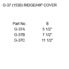
SNOW CONTROL


VALLEYS


RIDGE VENTS


PROFILE LIST


Typical Flashings
EAVE AND GABLE STARTERS


ENDWALLS


OTHER FLASHINGS


RIDGES


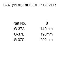
SNOW CONTROL


VALLEYS


RIDGE VENTS


Lo-Rib
Among the most economical panels on the market, Agway’s lightweight Lo-rib profile is ideal for use on high sloped roofs, or as exterior and interior siding. Lo-Rib installs easily and adds a professional finish to any structure. Available in a wide range of colours, Agway’s Lo Rib profile, combined with available trims, fasteners and other accessories, provides a complete solution for any project.
Measurement Type
Profile Picture


Specifications
| GAUGE | LENGTH | COVERAGE | ||
|---|---|---|---|---|
| MINIMUM | MAXIMUM | MINIMUM | MAXIMUM | |
| 30 | 24 | 10 | 600 | 37.55 |
| GAUGE | LENGTH | COVERAGE | ||
|---|---|---|---|---|
| MINIMUM | MAXIMUM | MINIMUM | MAXIMUM | |
| 30 | 24 | 254 | 15.24 | 954 |
Section Properties
| BASE STEEL THICKNESS |
WEIGHT G90 |
YIELD STRESS |
SECTION MODULUS |
DEFLECTION MOMENT OF INERTIA |
|
|---|---|---|---|---|---|
| in | psf | ksi | MID SPAN in 3 |
SUPPORT in 3 |
MID SPAN in 4 |
| 0.0120 | 0.560 | 80 | |||
| 0.0135 | 0.626 | 80 | |||
| 0.0180 | 0.813 | 50 | |||
| 0.0240 | 1.037 | 33 | |||
| BASE STEEL THICKNESS |
MASS Z275 |
YIELD STRESS |
SECTION MODULUS |
DEFLECTION MOMENT OF INERTIA |
|
|---|---|---|---|---|---|
| mm | kg/m | MPa | MID SPAN x10 3mm3 |
SUPPORT x10 3mm3 |
MID SPAN x10 3mm3 |
| 0.305 | 2.73 | 550 | |||
| 0.343 | 3.06 | 550 | |||
| 0.457 | 3.97 | 345 | |||
| 0.610 | 5.06 | 230 | |||

Diamond Rib
Available in 29 Ga to 22 Ga, Agway’s extremely popular and versatile Diamond rib profile can be used as a roof or wall cladding for your residential project. Diamond Rib is available in multiple colours and two widths, further enhancing it’s versatility.
Measurement Type
Profile Picture

- Steel conforms to ASTM A653.
- Section properties are in accordance with CSA-S136-07.
- Values in row “S” are based on strength.
- Values in row “D” are based on a deflection limit of 1/180 of the span.
- Web crippling not included in strength values. See example calculation in notes to designer.
- Contact the sales department for stocked colours and gauges.
- The load table contained on this data sheet was prepared by Dr. R.M. Schuster P.Eng. Professor Emeritus of Structural Engineering, University of Waterloo, Ontario, Canada.

- Steel conforms to ASTM A653.
- Section properties are in accordance with CSA-S136-07.
- Values in row “S” are based on strength.
- Values in row “D” are based on a deflection limit of 1/180 of the span.
- Web crippling not included in strength values. See example calculation in notes to designer.
- Contact the sales department for stocked colours and gauges.
- The load table contained on this data sheet was prepared by Dr. R.M. Schuster P.Eng. Professor Emeritus of Structural Engineering, University of Waterloo, Ontario, Canada.
Specifications
| GAUGE | LENGTH | COVERAGE | ||
|---|---|---|---|---|
| MINIMUM | MAXIMUM | MINIMUM | MAXIMUM | |
| 30 | 24 | 16 | 540 | 36 |
| 30 | 22 | 16 | 480 | 30 |
| GAUGE | LENGTH | COVERAGE | ||
|---|---|---|---|---|
| MINIMUM | MAXIMUM | MINIMUM | MAXIMUM | |
| 30 | 24 | 406 | 13.72 | 914 |
| 30 | 22 | 406 | 12.92 | 780 |
Section Properties
| BASE STEEL THICKNESS |
WEIGHT G90 |
YIELD STRESS |
SECTION MODULUS |
DEFLECTION MOMENT OF INERTIA |
|
|---|---|---|---|---|---|
| in | psf | ksi | MID SPAN in 3 |
SUPPORT in 3 |
MID SPAN in 4 |
| 0.0120 | 0.64 | 33 | 0.0221 | 0.0202 | 0.0144 |
| 0.0135 | 0.71 | 80 | 0.0227 | 0.0203 | 0.0152 |
| 0.0180 | 0.93 | 33 | 0.0381 | 0.0361 | 0.0227 |
| 0.0240 | 1.22 | 33 | 0.0550 | 0.0498 | 0.0302 |
| 0.0300 | 1.51 | 33 | 0.0683 | 0.0637 | 0.0376 |
| BASE STEEL THICKNESS |
MASS Z275 |
YIELD STRESS |
SECTION MODULUS |
DEFLECTION MOMENT OF INERTIA |
|
|---|---|---|---|---|---|
| mm | kg/m | MPa | MID SPAN x10 3mm3 |
SUPPORT x10 3mm3 |
MID SPAN x10 3mm3 |
| 0.305 | 3.11 | 230 | 1.19 | 1.09 | 0.0196 |
| 0.343 | 3.46 | 550 | 1.22 | 1.09 | 0.0207 |
| 0.457 | 4.52 | 230 | 2.04 | 1.94 | 0.0309 |
| 0.610 | 5.94 | 230 | 2.96 | 2.68 | 0.0412 |
| 0.762 | 7.36 | 230 | 3.67 | 3.42 | 0.0514 |


Century Rib
Economical and easy-to-install, Agway’s Century Rib profile is our most popular product for residential roof applications. Available in a wide range of colours, Agway’s Century Rib profile, combined with available trims, vents, fasteners and other accessories, provides a complete roofing solution for any project.
Measurement Type
Profile Picture

- Steel conforms to ASTM A653.
- Section properties are in accordance with CSA-S136-07.
- Values in row “S” are based on strength.
- Values in row “D” are based on a deflection limit of 1/180 of the span.
- Web crippling not included in strength values. See example calculation in notes to designer.
- Contact the sales department for stocked colours and gauges.
- The load table contained on this data sheet was prepared by Dr. R.M. Schuster P.Eng. Professor Emeritus of Structural Engineering, University of Waterloo, Ontario, Canada.

- Steel conforms to ASTM A653.
- Section properties are in accordance with CSA-S136-07.
- Values in row “S” are based on strength.
- Values in row “D” are based on a deflection limit of 1/180 of the span.
- Web crippling not included in strength values. See example calculation in notes to designer.
- Contact the sales department for stocked colours and gauges.
- The load table contained on this data sheet was prepared by Dr. R.M. Schuster P.Eng. Professor Emeritus of Structural Engineering, University of Waterloo, Ontario, Canada.
Specifications
| GAUGE | LENGTH | COVERAGE | ||
|---|---|---|---|---|
| MINIMUM | MAXIMUM | MINIMUM | MAXIMUM | |
| 30 | 24 | 16 | 540 | 36 |
| GAUGE | LENGTH | COVERAGE | ||
|---|---|---|---|---|
| MINIMUM | MAXIMUM | MINIMUM | MAXIMUM | |
| 30 | 24 | 406 | 13.72 | 914 |
Section Properties
| BASE STEEL THICKNESS |
WEIGHT G90 |
YIELD STRESS |
SECTION MODULUS |
DEFLECTION MOMENT OF INERTIA |
|
|---|---|---|---|---|---|
| in | psf | ksi | MID SPAN in 3 |
SUPPORT in 3 |
MID SPAN in 4 |
| 0.0120 | 0.64 | 33 | 0.0108 | 0.0091 | 0.0078 |
| 0.0135 | 0.71 | 80 | 0.0121 | 0.0099 | 0.0088 |
| 0.0180 | 0.93 | 33 | 0.0161 | 0.0144 | 0.0117 |
| 0.0240 | 1.22 | 33 | 0.0213 | 0.0199 | 0.0155 |
| BASE STEEL THICKNESS |
MASS Z275 |
YIELD STRESS |
SECTION MODULUS |
DEFLECTION MOMENT OF INERTIA |
|
|---|---|---|---|---|---|
| mm | kg/m | MPa | MID SPAN x10 3mm3 |
SUPPORT x10 3mm3 |
MID SPAN x10 3mm3 |
| 0.305 | 3.11 | 230 | 0.581 | 0.487 | 0.0102 |
| 0.343 | 3.46 | 550 | 0.653 | 0.530 | 0.0115 |
| 0.457 | 4.52 | 230 | 0.865 | 0.775 | 0.0153 |
| 0.610 | 5.94 | 230 | 1.14 | 1.07 | 0.0204 |


Product Sheet
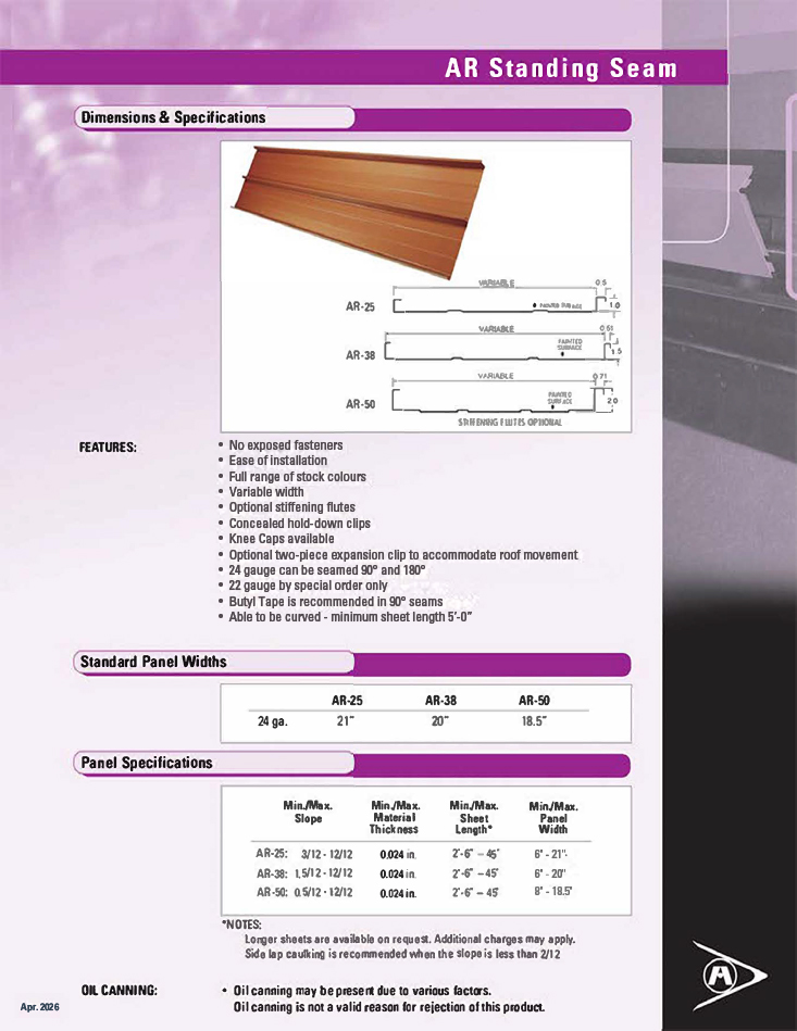
AR Standing Seam
Our Standing Seam AR metal roofing is available in 24 gauge, in variable widths and with side lap rib heights of 1”, 1 ½” or 2” (27.94 mm, 38.1 mm or 50.8 mm). Agway’s AR series also features optional, two-piece expansion clips to accommodate movement of the roof, and can be seamed at either 90º or180º. With a 180º seam and optional seam caulking, panels can be used on low slopes (AR-38 down to 1.5/12 and AR-50 down to 0.5/12).
Unlike many traditional alternatives like slate or tile, our Standing Seam Profile is easy to install, more cost effective, 100% recyclable and facilitates more creativity in design. In fact, this profile can even be curved!
Whether you choose a profile from our Standing Seam, Nail Strip, or Snap Lock roof cladding systems, the result will be a stunning, architecturally distinctive roof that installs easily and has no exposed fasteners. All these durable Agway roof cladding products are available in a full range of stock colours, in variable panel widths, and with optional stiffening flutes. All are single skin applications and must be applied over a solid substrate and waterproof membrane, using clips at a maximum of 2’ centres. A full range of flashings and accessories are available from Agway to complete your project.
Resources
Measurement Type
Profile Picture
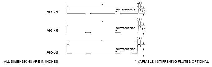
Panel Specifications
| MIN/MAX | MIN/MAX | MIN/MAX | MIN/MAX | |
|---|---|---|---|---|
| SLOPE | MATERIAL THICKNESS | SHEET LENGTH | PANEL WIDTH | |
| AR-25 | 3/12 – 12/12 | 0.018 – 0.030″ | 2′ 6″ – 45′ | 6″ – 21” |
| AR-38 | 1.5/12 – 12/12 | 0.018 – 0.030″ | 2′ 6″ – 45′ | 6″ – 20” |
| AR-50 | 0.5/12 – 12/12 | 0.018 – 0.030″ | 2′ 6″ – 45′ | 8″ – 18.5” |
- Side lap caulking is recommended when the slope is less than 2/12
- Longer sheets are available. Additional charges may apply.
- For AR-25, AR-38 or AR-50 with 180 degree seam – maximum gauge is 24 GA
- Short sheet charge for any lengths under 48”
Standard Panel Widths
| GAUGE | AR-25 | AR-38 | AR-50 |
|---|---|---|---|
| 24 | 21″ | 20″ | 18.5″ |
Features
- No exposed fasteners
- Ease of installation
- Full range of stock colours
- Variable width
- Optional stiffening flutes
- Concealed hold-down clips
- Knee Caps available
- Optional two-piece expansion clip to accommodate roof movement
- 24 gauge can be seamed 90° and 180°
- 22 gauge by special order only
- Butyl Tape is recommended in 90° seams
- Able to be curved – minimum sheet length 5’-0”
Oil Canning
- Oil Canning is naturally occurring phenomenon inherent in all sheet steel.
- Oil Canning is not a valid reason for rejection of these products
Installation
- Single skin application
- Recommended that this always be applied over solid substrate
- Recommended that AR Series profiles be applied over waterproof membrane
- Clips at maximum 2’ centers – 2 fasteners per clip
- Mechanical and Hand Seamer required. For seamer purchase & rental visit the D.I. Roof Seamers website – or by calling D.I. Roof Installers at 1-888-343-0456
Hold-Down Clip Detail

Overlap Seaming Options

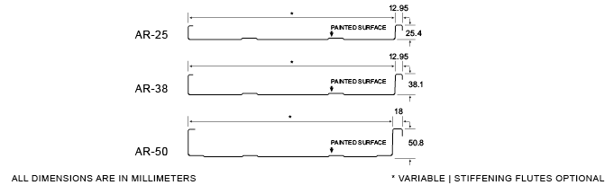
Panel Specifications
| MIN/MAX | MIN/MAX | MIN/MAX | MIN/MAX | |
|---|---|---|---|---|
| SLOPE | MATERIAL THICKNESS | SHEET LENGTH | PANEL WIDTH | |
| AR-25 | 3/12 – 12/12 | 0.457 – 0.762 mm | 0.76 – 13.71 m | 152 – 533 mm |
| AR-38 | 1.5/12 – 12/12 | 0.457 – 0.762 mm | 0.76 – 13.71 m | 152 – 509 mm |
| AR-50 | 0.5/12 – 12/12 | 0.457 – 0.762 mm | 0.76 – 13.71 m | 203 – 470 mm |
- Side lap caulking is recommended when the slope is less than 2/12
- Longer sheets are available. Additional charges may apply.
- For AR-25, AR-38 or AR-50 with 180 degree seam – maximum gauge is 24 GA
- Short sheet charge for any lengths under 1,219 mm
Standard Panel Widths
| GAUGE | AR-25 | AR-38 | AR-50 |
|---|---|---|---|
| 24 | 533 mm | 509 mm | 470 mm |
Features
- No exposed fasteners
- Ease of installation
- Full range of stock colours
- Variable width
- Optional stiffening flutes
- Concealed hold-down clips
- Knee Caps available
- Optional two-piece expansion clip to accommodate roof movement
- 24 gauge can be seamed 90° and 180°
- 22 gauge by special order only
- Butyl Tape is recommended in 90° seams
- Able to be curved – minimum sheet length: 1.52m
Oil Canning
- Oil Canning is naturally occurring phenomenon inherent in all sheet steel.
- Oil Canning is not a valid reason for rejection of these products
Installation
- Single skin application
- Recommended that AR Series profiles be applied over waterproof membrane
- Recommended that this be applied over waterproof membrane
- Clips at maximum 610 mm centers – 2 fasteners per clip
- Mechanical and Hand Seamer required. For seamer purchase & rental visit the D.I. Roof Seamers website – or by calling D.I. Roof Installers at 1-888-343-0456
Hold-Down Clip Detail
Overlap Seaming Options


Product Sheet

Platinum HT-SA Underlayment
Introducing PLATINUM HT-SA our premium high temperature self- adhering roofing underlayment that combines the superior slip resistant GRIPSPOT technology developed by FT Synthetics with a high strength high temperature modified rubberized asphalt backing that has both low temperature (40°F / 4.4°C) deck adhesion, high temperature flow stability (240°F / 115°C) and a limited lifetime warranty. In addition, PLATINUM HT-SA has a split release silicone liner and a synthetic construction to inhibit mold growth.
PLATINUM HT-SA can be used in most types on installations whether they are commercial or residential. It can be used under metal, wood, asphalt & synthetic shingles, slate or tiles. PLATINUM HT-SA meets and exceeds required industry standards.
- GRIPSPOT Technology for superior slip resistance
- Silicone treated split release line
- High temperature resistant to 240°F (115°C)
- Deck adhesion at 40°F (4.4°C)
- 180 day UV resistant
- Synthetic construction to inhibit mold growth
- NEW! LIFETIME limited warranty
- Meets and exceeds ASTM D1970
Specifications

Technical Data

Installation Instruction
Caution: Always follow Safety Instruction, Building Codes and Safe Work Practices issues by the local Govt. bodies (e.g. OSHA / WCB)
PLATINUM HT-SA must be covered by a primary roof (Asphalt & Synthetic Shingles, Metal Roofing, Tiles, Slate, and Cedar Shakes) within 180 days. For best results HT-SA should be installed on a dry deck when the air, membrane, and substrate temperature is over 40°F (4.4°C). Priming is not required for attaching to wood deck when the temperature is above 40°F. Concrete and masonry decks should be primed with a solvent or a water based primer that meets ASTM D41 for asphalt based self-adhesive membranes.
For cold weather applications below 40°F (4.4°C) a primer should be used and the laps blind nailed. Blind nail with 3/8” head roofing nails of 1” or longer in the 3” over lap area.
HT-SA is recommend for roof slope applications 2:12 and above. For steep slope applications (6:12 or greater) or when installing at temperatures greater than 100°F (38°C) it is recommended to blind nail the overlap area as instructed above for cold weather applications.
HT-SA is to be laid out horizontally (parallel) to the eave with the printed side up, using 3″ side laps and 6″ end laps.
HT-SA may also be installed vertically. For vertical installation anchor with 3/8” head roofing nails along the upper most edge 3 inches down with 6 equally spaced nails across the 36” width. Ensure roofing nails are perpendicular to the roof deck so that the head lays flat and seals well to the top surface of the HT-SA using 3″ side laps and 6″ end laps.
Always work from the low point to the high point of the roof. Apply the membrane in valleys before the membrane is applied to the eaves.
Cut HT-SA to manageable lengths and position parallel to the edge of the roof. Peel back one side of the split release sheet approximately 4 in (10 cm) then apply as positioned to the roof deck. Continue peeling back one side of the split release sheet. Press down on HT-SA with a small rubber roller to increase adhesion to the roof deck. Peel back the remaining half of the split release liner and press down on the HT-SA to adhere to the roof deck again using a small roller to improve adhesion.
For eave installation HT-SA should be applied over the metal drip edge at the eave. Do not fold HT-SA over the roof edge unless the edge is subsequently covered over by a drip edge or other flashing material. It is recommended that HT-SA extend from the eave up the roof to a point 24” inside the exterior wall. This should be above the maximum ice dam buildup line in most areas. Consult your local building code for specific requirements.
For high elevation, high wind or wind driven rain it is recommended to cover the entire roof deck with HT-SA.
Safety Notification:
FT Synthetics Products are designed with the GRIPSPOT technology for better skid protection for the roofer but product may become slippery due to high moisture, frost, rain, water, dust, debris or other conditions. Use precautions when working on the roof. Follow all local and federal safety codes when installing any roofing system including FT Synthetics products. Failure to adhere to those procedures may result in serious injury or even death.
